Maximum Connected Load
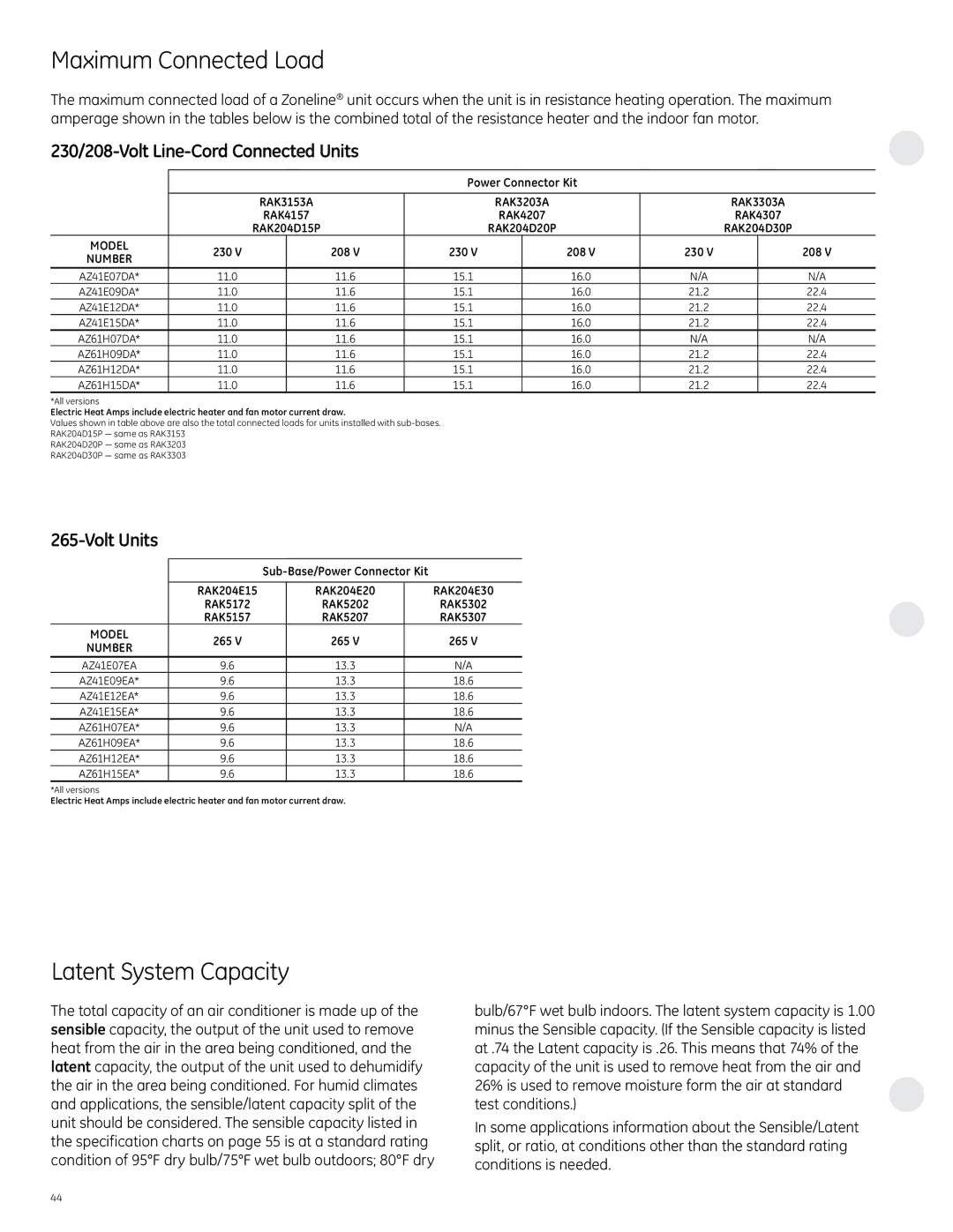
The maximum connected load of a Zoneline® unit occurs when the unit is in resistance heating operation. The maximum amperage shown in the tables below is the combined total of the resistance heater and the indoor fan motor.
230/208-Volt Line-Cord Connected Units
|
|
|
| Power Connector Kit |
|
|
| ||
|
|
|
|
|
|
|
|
|
|
|
| RAK3153A |
| RAK3203A |
| RAK3303A | |||
|
| rak4157 |
| RAK4207 |
| RAK4307 | |||
|
| rak204d15p |
| RAK204D20P |
| RAK204D30P | |||
MODEL | 230 V |
| 208 V | 230 V |
| 208 V | 230 V |
| 208 V |
NUMBER |
|
|
| ||||||
|
|
|
|
|
|
|
|
| |
AZ41E07DA* | 11.0 |
| 11.6 | 15.1 |
| 16.0 | N/A |
| N/A |
AZ41E09DA* | 11.0 |
| 11.6 | 15.1 |
| 16.0 | 21.2 |
| 22.4 |
AZ41E12DA* | 11.0 |
| 11.6 | 15.1 |
| 16.0 | 21.2 |
| 22.4 |
AZ41E15DA* | 11.0 |
| 11.6 | 15.1 |
| 16.0 | 21.2 |
| 22.4 |
AZ61H07DA* | 11.0 |
| 11.6 | 15.1 |
| 16.0 | N/A |
| N/A |
AZ61H09DA* | 11.0 |
| 11.6 | 15.1 |
| 16.0 | 21.2 |
| 22.4 |
AZ61H12DA* | 11.0 |
| 11.6 | 15.1 |
| 16.0 | 21.2 |
| 22.4 |
AZ61H15DA* | 11.0 |
| 11.6 | 15.1 |
| 16.0 | 21.2 |
| 22.4 |
*All versions
Electric Heat Amps include electric heater and fan motor current draw.
Values shown in table above are also the total connected loads for units installed with
RAK204D15P — same as RAK3153
RAK204D20P — same as RAK3203
RAK204D30P — same as RAK3303
265-Volt Units
|
|
| |||
|
|
|
|
|
|
| RAK204E15 |
| RAK204E20 |
| RAK204E30 |
| RAK5172 |
| RAK5202 |
| RAK5302 |
| RAK5157 |
| RAK5207 |
| RAK5307 |
MODEL | 265 V |
| 265 V |
| 265 V |
NUMBER |
|
| |||
|
|
|
|
| |
AZ41E07EA | 9.6 |
| 13.3 |
| N/A |
AZ41E09EA* | 9.6 |
| 13.3 |
| 18.6 |
AZ41E12EA* | 9.6 |
| 13.3 |
| 18.6 |
AZ41E15EA* | 9.6 |
| 13.3 |
| 18.6 |
AZ61H07EA* | 9.6 |
| 13.3 |
| N/A |
AZ61H09EA* | 9.6 |
| 13.3 |
| 18.6 |
AZ61H12EA* | 9.6 |
| 13.3 |
| 18.6 |
AZ61H15EA* | 9.6 |
| 13.3 |
| 18.6 |
*All versions
Electric Heat Amps include electric heater and fan motor current draw.
Latent System Capacity
The total capacity of an air conditioner is made up of the sensible capacity, the output of the unit used to remove heat from the air in the area being conditioned, and the latent capacity, the output of the unit used to dehumidify the air in the area being conditioned. For humid climates and applications, the sensible/latent capacity split of the unit should be considered. The sensible capacity listed in the specification charts on page 55 is at a standard rating condition of 95°F dry bulb/75°F wet bulb outdoors; 80°F dry
bulb/67°F wet bulb indoors. The latent system capacity is 1.00 minus the Sensible capacity. (If the Sensible capacity is listed at .74 the Latent capacity is .26. This means that 74% of the capacity of the unit is used to remove heat from the air and 26% is used to remove moisture form the air at standard test conditions.)
In some applications information about the Sensible/Latent split, or ratio, at conditions other than the standard rating conditions is needed.
44