Zoneline® Chassis Nomenclature
The Zoneline chassis is identified by a model number defining the type of unit, cooling capacity, electrical information and optional features included on the unit. When specifying or
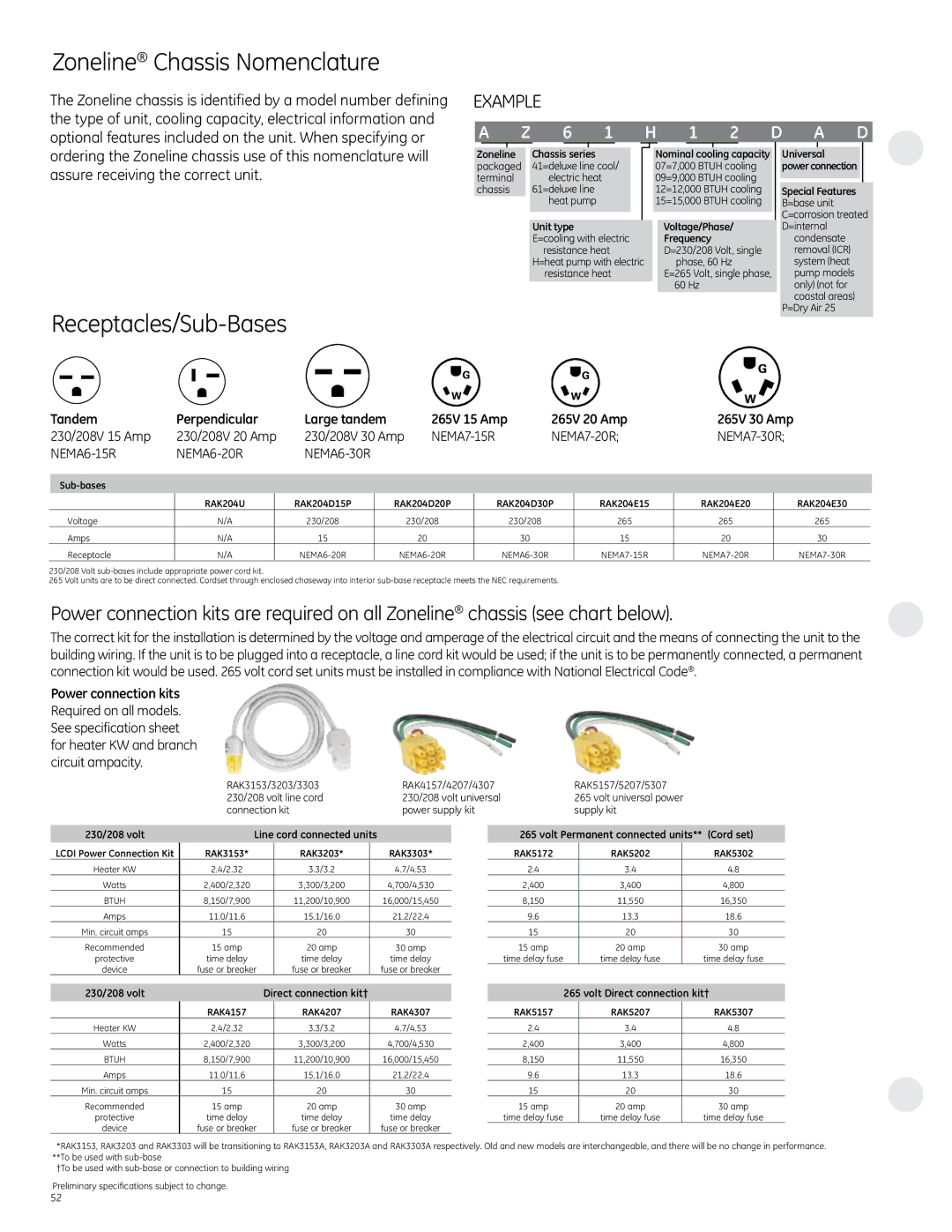
EXAMPLE
A Z 6 1 H 1 2 D A D
ordering the Zoneline chassis use of this nomenclature will assure receiving the correct unit.
Receptacles/Sub-Bases
Zoneline |
| Chassis series |
packaged |
| 41=deluxe line cool/ |
terminal |
| electric heat |
chassis |
| 61=deluxe line |
|
| heat pump |
|
|
|
Unit type
E=cooling with electric resistance heat
H=heat pump with electric resistance heat
Nominal cooling capacity |
| Universal |
| |
07=7,000 BTUH cooling |
| power connection |
| |
09=9,000 BTUH cooling |
|
|
| |
|
|
| ||
12=12,000 BTUH cooling |
| Special Features | ||
15=15,000 BTUH cooling |
| B=base unit | ||
|
|
| C=corrosion treated | |
| Voltage/Phase/ |
| D=internal | |
| Frequency |
| condensate | |
| D=230/208 Volt, single |
| removal (ICR) | |
| phase, 60 Hz |
| system (heat | |
| E=265 Volt, single phase, |
| pump models | |
| 60 Hz |
| only) (not for | |
|
|
| coastal areas) | |
|
|
| P=Dry Air 25 | |
|
|
|
|
|
Tandem | Perpendicular | Large tandem |
| 265V 15 Amp | 265V 20 Amp | 265V 30 Amp |
| ||||||
230/208V 15 Amp | 230/208V 20 Amp | 230/208V 30 Amp |
|
| |||||||||
|
|
|
|
|
|
|
|
|
|
|
| ||
|
|
|
|
|
|
|
|
|
|
|
|
|
|
|
|
|
|
|
|
|
|
|
|
|
|
|
|
| RAK204U |
| RAK204D15P |
| RAK204D20P |
| RAK204D30P | RAK204E15 | RAK204E20 |
| RAK204E30 | ||
Voltage | N/A |
| 230/208 |
|
| 230/208 |
| 230/208 |
| 265 | 265 |
| 265 |
Amps | N/A |
| 15 |
|
| 20 |
| 30 |
| 15 | 20 |
| 30 |
Receptacle | N/A |
|
|
|
|
|
|
|
|
|
| ||
230/208 Volt
265 Volt units are to be direct connected. Cordset through enclosed chaseway into interior
Power connection kits are required on all Zoneline® chassis (see chart below).
The correct kit for the installation is determined by the voltage and amperage of the electrical circuit and the means of connecting the unit to the building wiring. If the unit is to be plugged into a receptacle, a line cord kit would be used; if the unit is to be permanently connected, a permanent connection kit would be used. 265 volt cord set units must be installed in compliance with National Electrical Code®.
Power connection kits Required on all models. See specification sheet for heater KW and branch circuit ampacity.
RAK3153/3203/3303 | RAK4157/4207/4307 | RAK5157/5207/5307 |
230/208 volt line cord | 230/208 volt universal | 265 volt universal power |
connection kit | power supply kit | supply kit |
230/208 volt | Line cord connected units |
| ||
LCDI Power Connection Kit | RAK3153* | RAK3203* |
| RAK3303* |
Heater KW | 2.4/2.32 | 3.3/3.2 |
| 4.7/4.53 |
Watts | 2,400/2,320 | 3,300/3,200 |
| 4,700/4,530 |
BTUH | 8,150/7,900 | 11,200/10,900 |
| 16,000/15,450 |
Amps | 11.0/11.6 | 15.1/16.0 |
| 21.2/22.4 |
Min. circuit amps | 15 | 20 |
| 30 |
Recommended | 15 amp | 20 amp |
| 30 amp |
protective | time delay | time delay |
| time delay |
device | fuse or breaker | fuse or breaker |
| fuse or breaker |
265 volt Permanent connected units** (Cord set)
RAK5172 | RAK5202 | RAK5302 |
2.4 | 3.4 | 4.8 |
2,400 | 3,400 | 4,800 |
8,150 | 11,550 | 16,350 |
9.6 | 13.3 | 18.6 |
15 | 20 | 30 |
15 amp | 20 amp | 30 amp |
time delay fuse | time delay fuse | time delay fuse |
230/208 volt |
| Direct connection kit† |
| |
| RAK4157 |
| RAK4207 | RAK4307 |
Heater KW | 2.4/2.32 |
| 3.3/3.2 | 4.7/4.53 |
Watts | 2,400/2,320 |
| 3,300/3,200 | 4,700/4,530 |
BTUH | 8,150/7,900 |
| 11,200/10,900 | 16,000/15,450 |
Amps | 11.0/11.6 |
| 15.1/16.0 | 21.2/22.4 |
Min. circuit amps | 15 |
| 20 | 30 |
Recommended | 15 amp |
| 20 amp | 30 amp |
protective | time delay |
| time delay | time delay |
device | fuse or breaker |
| fuse or breaker | fuse or breaker |
265 volt Direct connection kit†
RAK5157 | RAK5207 | RAK5307 |
2.4 | 3.4 | 4.8 |
2,400 | 3,400 | 4,800 |
8,150 | 11,550 | 16,350 |
9.6 | 13.3 | 18.6 |
15 | 20 | 30 |
15 amp | 20 amp | 30 amp |
time delay fuse | time delay fuse | time delay fuse |
*RAK3153, RAK3203 and RAK3303 will be transitioning to RAK3153A, RAK3203A and RAK3303A respectively. Old and new models are interchangeable, and there will be no change in performance. **To be used with
†To be used with
Preliminary specifications subject to change.
52