STEP 2
PRE*RE FOR ELECTRIUL CONNECTION
Use only a
The electrical rating of the cord must be 125/250 volts minimum, 40 amperes.
NOTE: Only a
STEP 3
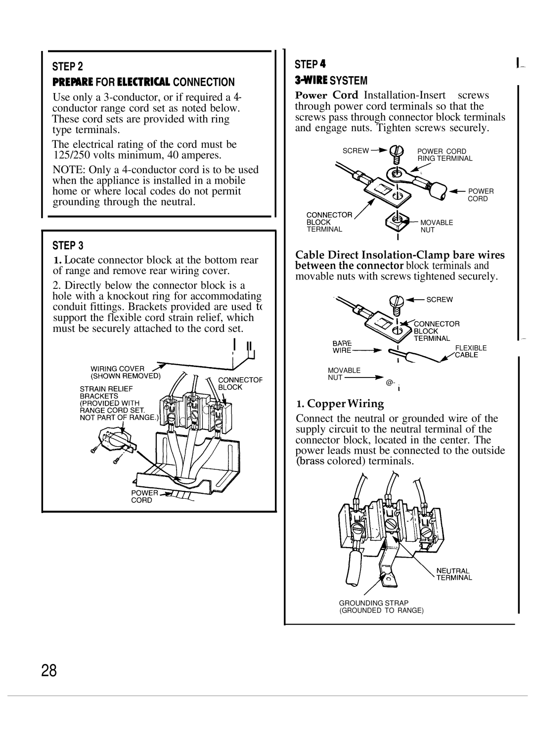
1.hcate connector block at the bottom rear of range and remove rear wiring cover.
2.Directly below the connector block is a hole with a knockout ring for accommodating conduit fittings. Brackets provided are used t( support the flexible cord strain relief, which must be securely attached to the cord set.
I II
STEP 4
3WIRE SYSTEM
Power Cord
SCREW + |
| POWER CORD |
| 9 | RING TERMINAL |
|
|
&L
+&+ POWER
>% CORD
:~:::CTOR
MOVABLE
TERMINAL* NUT I
Cable Direct
FLEXIBLE
MOVABLE
NUT ~ @- i
1.Copper Wiring
Connect the neutral or grounded wire of the supply circuit to the neutral terminal of the connector block, located in the center. The power leads must be connected to the outside @rass colored) terminals.
UTRAL
RMINAL
GROUNDING STRAP (GROUNDED TO RANGE)
1-
—
28
