Manuals
/
GE
/
Kitchen Appliance
/
Range
GE
JGBS80 Installation Instructions, 3ELECTRICAL CONNECTIONS CONT, 4SEAL THE OPENINGS
Models:
JGBS80
1
35
88
88
Download
88 pages
25.62 Kb
32
33
34
35
36
37
38
39
Troubleshooting
Install
To Set the Kitchen Timer
Warranty
Dimension
Problem
Parts and Accessories
assembly Electrode
To Adjust the Thermostat
Care and cleaning of the range
Page 35
Image 35
Page 34
Page 36
Page 35
Image 35
Page 34
Page 36
Contents
Care and Cleaning
ge.com
Non-Self-CleaningGas
Safety Instructions
ANTI-TIPDEVICE
IMPORTANT SAFETY INFORMATION
READ ALL INSTRUCTIONS BEFORE USING
Safety Instructions
Safety Instructions Operating Instructions
IMPORTANT SAFETY NOTICE
SAFETY PRECAUTIONS
SAFETY PRECAUTIONS
WARNING: NEVER use this
Instructions
Consumer Support
Safety Instructions Operating
COOK MEAT AND POULTRY THOROUGHLY…
OVEN
WARNING: NEVER cover
Safety Instructions
SURFACE BURNERS
IMPORTANT SAFETY INFORMATION
READ ALL INSTRUCTIONS BEFORE USING
Operating Instructions Installation Instructions
READ AND FOLLOW THIS SAFETY INFORMATION CAREFULLY
Troubleshooting Tips Consumer Support
SAVE THESE INSTRUCTIONS
Features and appearance may vary from your model
Features of your range
Instructions Operating
Instructions
Using the gas surface burners
Tips Installation
Support Troubleshooting
How to Select Flame Size
Safety Instructions
Support
Operating Instructions Installation
Using the Griddle
Using the griddle
Safety Instructions
How to Insert the Griddle
To Change or Cancel the Kitchen Timer Setting
Using the clock and timer
Troubleshooting Tips Consumer Support
To Set the Kitchen Timer
Troubleshooting Tips Installation
Using the oven
Instructions Safety
Power Outage
How to Set the Oven for Baking or Roasting
Safety
Installation
Tips Consumer Support
Instructions
Consumer Support Troubleshooting Tips
Using the oven
Using Aluminum Foil
ge.com
Safety
Broiling Guide
Instructions Operating Instructions
To Adjust the Thermostat
Adjust the oven thermostat—Doit yourself
Instructions Operating Instructions
Safety Instructions
Griddle
Care and cleaning of the range
Safety Instructions
Griddle Precautions
Side Grate Burner cap Burner head Electrode
Care and cleaning of the range
assembly Electrode
Burner Assemblies
Tips Consumer Support
After cleaning
Replacement
Safety
Cooktop Surface
Care and cleaning of the range
Consumer Support
Burner Grates
To clean the outside of the door
Troubleshooting Tips
Safety
To clean the inside of the door
Oven Light Replacement
Care and cleaning of the range
Tips Installation
Consumer Support Troubleshooting
Be careful where the oven cleaner is sprayed
Safety Instructions
Operating Instructions Installation
Cautions about using spray-onoven cleaners
Read these instructions completely and carefully
Installation Instructions
Range
•IMPORTANT – Save these
PART INCLUDED
Installation Instructions
FOR YOUR SAFETY
TOOLS YOU WILL NEED
LESS THAN 24 INCHES
Installation Instructions
WARNING! INSTALLATION SAFETY INSTRUCTIONS
Read these instructions completely and carefully
DIMENSIONS AND CLEARANCES
Installation Instructions
All ranges can tip and injury could result
ANTI-TIPDEVICE
Installation Instructions
Take the accessory pack out of the oven
1PROVIDE ADEQUATE GAS SUPPLY
Installation Instructions
2CONNECT THE RANGE TO GAS
GAS PIPE AND ELECTRICAL OUTLET LOCATIONS
Installation Instructions
GAS PIPE AND ELECTRICAL OUTLET LOCATIONS
for model JGBS80 only—seebelow for model JGBS09
Installer: Inform
Installation Instructions
Installer: Inform
Installer Inform
Electrical Requirements
Installation Instructions
3ELECTRICAL CONNECTIONS
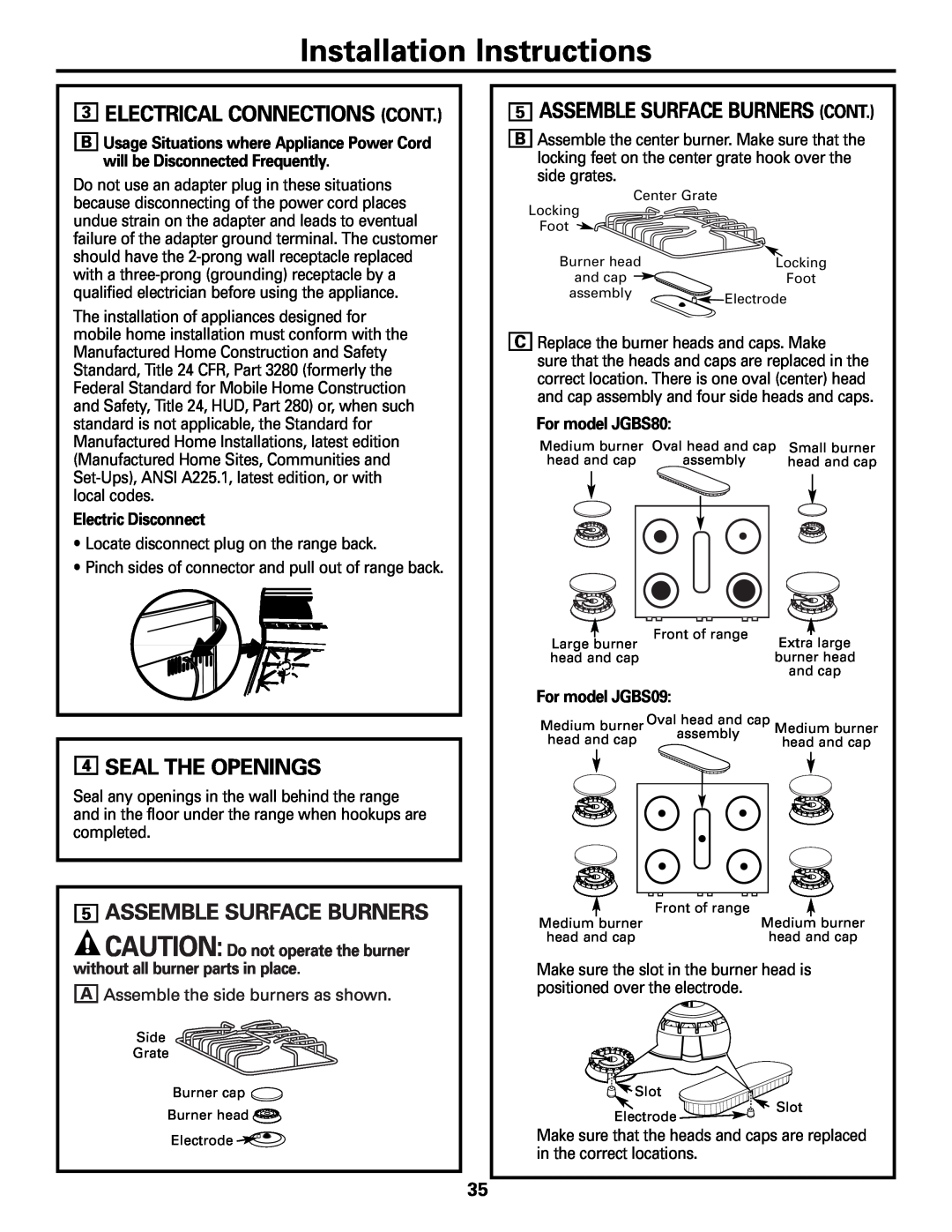
3ELECTRICAL CONNECTIONS CONT
5ASSEMBLE SURFACE BURNERS
Installation Instructions
3ELECTRICAL CONNECTIONS CONT
4SEAL THE OPENINGS
Electric Ignition Models
Installation Instructions
6CHECK IGNITION OF SURFACE BURNERS
7CHECK IGNITION OF OVEN BURNER
To remove the oven bottom
Installation Instructions
9LEVELING THE RANGE
WHEN ALL HOOKUPS ARE COMPLETED
Installation Instructions
10INSTALLING THE ANTI-TIPDEVICE
10INSTALLING THE ANTI-TIPDEVICE CONT
Possible Causes
Before you call for service…
Problem
See the Care and cleaning of the range section
• See the Installation of the range section
Before you call for service…
Problem
• See the Care and cleaning of the range section
Louisville, KY
GE Service Protection Plus
Warranty Registration Department P.O. Box
General Electric Company
Consumer Product Ownership Registration
Model Number
Serial Number
Consumer Product Ownership Registration
GE Will Replace
GE Gas Range Warranty
Safety Instructions Operating
Instructions Installation
GE Appliances Website
Schedule Service
Parts and Accessories
Consumer Support
Instrucciones de
Solucionar problemas . . .39–41
No Limpieza Automática Estufas a Gas
ge.com
DISPOSITIVO ANTI-VOLCADURA
ADVERTENCIA
INSTRUCCIONES IMPORTANTES DE SEGURIDAD
—QUE HACER SI PERCIBE OLOR A GAS
ADVERTENCIA
AVISO IMPORTANTE DE SEGURIDAD
PRECAUCIONES DE SEGURIDAD
Solucionar problemas
PRECAUCIONES DE SEGURIDAD
ADVERTENCIA: NUNCA
Solucionar problemas
INSTRUCCIONES IMPORTANTES DE SEGURIDAD
Solucionar problemas
COCINE LA CARNE Y EL POLLO COMPLETAMENTE
HORNO
ADVERTENCIA: NUNCA
INSTRUCCIONES IMPORTANTES DE SEGURIDAD
QUEMADORES
Solucionar problemas
ADVERTENCIA
Seguridad
GUARDE ESTAS INSTRUCCIONES
problemas
Operación
Solucionar problemas
Características de la estufa
Seguridad
Operación
instalación
Solucionar problemas
Seguridad
Operación
Operación
Solucionar problemas
Cómo cocinar en el quemador a gas
Seguridad
problemas
Solucionar
Soporte
al consumidor
Seguridad
Plancha para asar
PRECAUCIÓN: Coloque y
Solucionar problemas
Operación
Utilización del reloj y cronómetro
problemas
Seguridad
Seguridad
problemas
Cómo usar el horno
PRECAUCIÓN: No intente
Instrucciones
Solucionar problemas
Soporte al consumidor
instalación
Operación
Solucionar problemas
Cómo usar el horno
Seguridad
instalación
Solucionar problemas
Operación
Soporte al consumidor
Instrucciones de
Solucionar problemas
Seguridad
Operación
Operación
Cuidado y limpieza
Solucionar problemas
Seguridad
Operación
PRECAUCIÓN: No opere
Solucionar problemas
Cuidado y limpieza
Operación
consumidor
Solucionar problemas
Seguridad
instalación
problemas
Cuidado y limpieza
Operación
Operación
PRECAUCIÓN: No limpie la
Solucionarproblemas
Seguridad
Cuidado y limpieza
PRECAUCIÓN: Antes de
Instruccionesde
problemas
Instrucciones
Solucionar problemas
Soporte al consumidor
instalación
Lea estas instrucciones completa y cuidadosamente
Instrucciones de instalación
Estufa
•IMPORTANTE – Guarde estas
PARTE INCLUIDA
Instrucciones de instalación
POR SU SEGURIDAD
MATERIALES QUE PUEDE NECESITAR
PRECAUCIÓN - No se deben
ADVERTENCIA INSTRUCCIONES DE SEGURIDAD DE
INSTALACIÓN
PRECAUCIÓN - No intente
Instrucciones de instalación
DIMENSIONES Y TOLERANCIAS
LOCALIZACIÓN MODELO Y NÚMERO DE SERIE
ADVERTENCIA DISPOSITIVO ANTI-VOLCADURA
Instrucciones de instalación
LOCALIZACIÓN
2CONECTE LA ESTUFA AL GAS cont
ADVERTENCIA: NO USE UNA
Instrucciones de instalación
2CONECTE LA ESTUFA AL GAS
de la pared posterior
Instrucciones de instalación
Conexión alterna
Instrucciones de instalación
Requisitos eléctricos
Instrucciones de instalación
3CONEXIONES ELÉCTRICAS
3CONEXIONES ELÉCTRICAS CONT
quemador sin antes colocar todas las partes
PRECAUCIÓN: No opere el
Instrucciones de instalación
Desconexión eléctrica
Modelos con ignición eléctrica
Instrucciones de instalación
6REVISAR IGNICIÓN DE QUEMADORES DE LA SUPERFICIE
7REVISE LA IGNICIÓN DEL QUEMADOR DEL HORNO
Para retirar el fondo del horno
Instrucciones de instalación
NECESARIO
9NIVELACIÓN DE LA ESTUFA
o convertir de nuevo a gas natural
ADVERTENCIA
Instrucciones de instalación
CUANDO TODA LA INSTALACIÓN ESTÉ COMPLETA
Seguridad
Antes de llamar para solicitar servicio…
Solucionar problemas
Problema
• Ver la sección Para configurar el reloj
Seguridad Operación
Solucionar problemas
Problema
Soporte al consumidor
Solucionar problemas
Problema
Seguridad Operación
Operación
Notas
Instrucciones de instalación
Solucionar problemas
instalación
Garantía de GE para su estufa a gas
Solucionar problemas
Seguridad
Garantías ampliadas
Soporte al consumidor
Página Web de GE Appliances
Solicite una reparación
Top
Page
Image
Contents