Keypad Assembly
PDW9700 Series and PDW9900 Series
Top control models have a membrane keypad that is accessed by removing the door panel. (see Door Panel.)
•When removing the membrane keypad, peel the keypad from right to left.
•When installing, make sure the membrane button areas and lights align with the keypad.
•On models with an LED display, the display is held in place by 2 Phillips head screws.
Note: When replacing the keypad membrane, always run the Factory Test Mode to calibrate the keypad membrane to the control board.
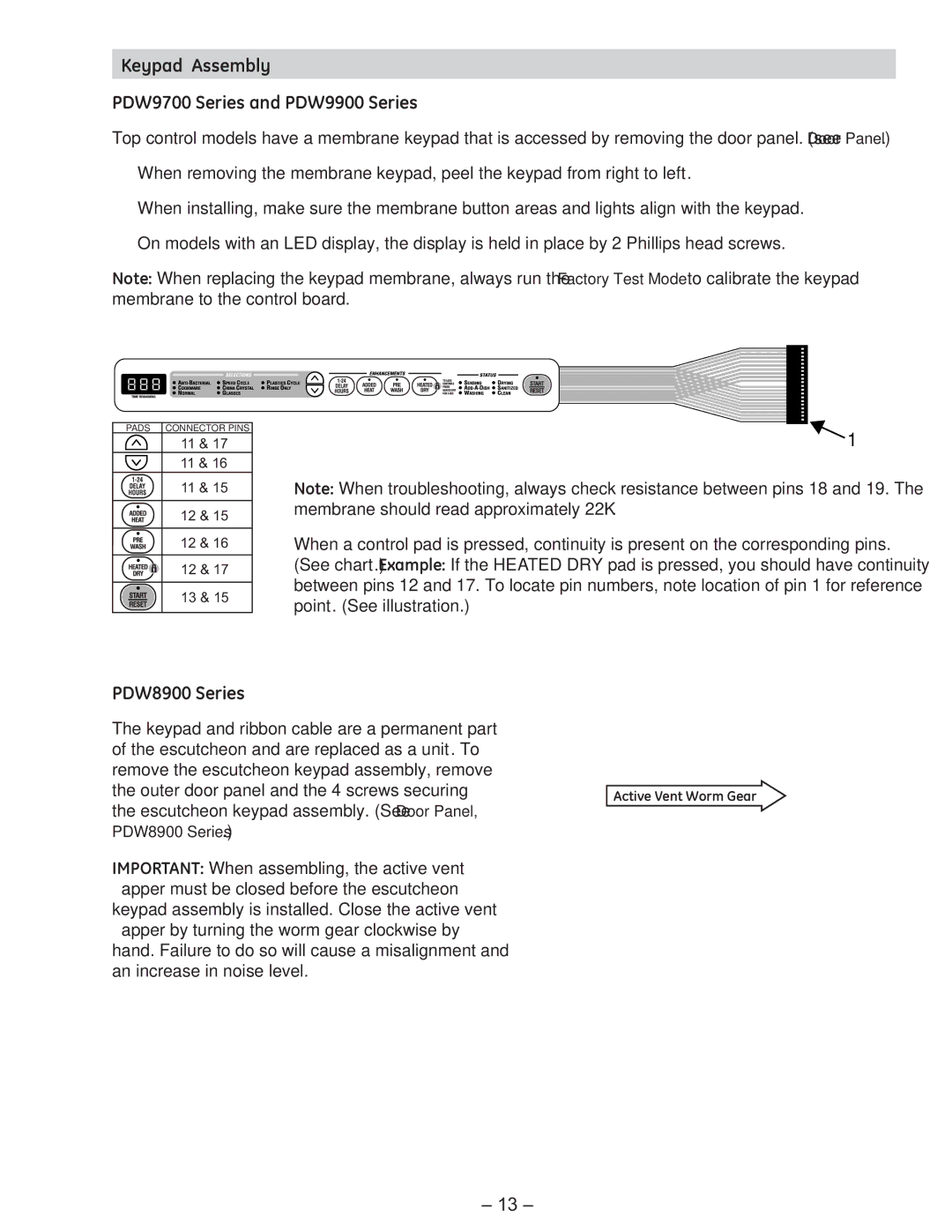
PADS CONNECTOR PINS
11 & 17
11 & 16
11 & 15
12 & 15
12 & 16
12 & 17
13 & 15
1
Note: When troubleshooting, always check resistance between pins 18 and 19. The membrane should read approximately 22K Ω.
When a control pad is pressed, continuity is present on the corresponding pins. (See chart.) Example: If the HEATED DRY pad is pressed, you should have continuity between pins 12 and 17. To locate pin numbers, note location of pin 1 for reference point. (See illustration.)
PDW8900 Series
The keypad and ribbon cable are a permanent part of the escutcheon and are replaced as a unit. To remove the escutcheon keypad assembly, remove
the outer door panel and the 4 screws securingActive Vent Worm Gear the escutcheon keypad assembly. (See Door Panel,
PDW8900 Series.)
IMPORTANT: When assembling, the active vent flapper must be closed before the escutcheon keypad assembly is installed. Close the active vent flapper by turning the worm gear clockwise by hand. Failure to do so will cause a misalignment and an increase in noise level.
– 13 –