Turbidity Sensor
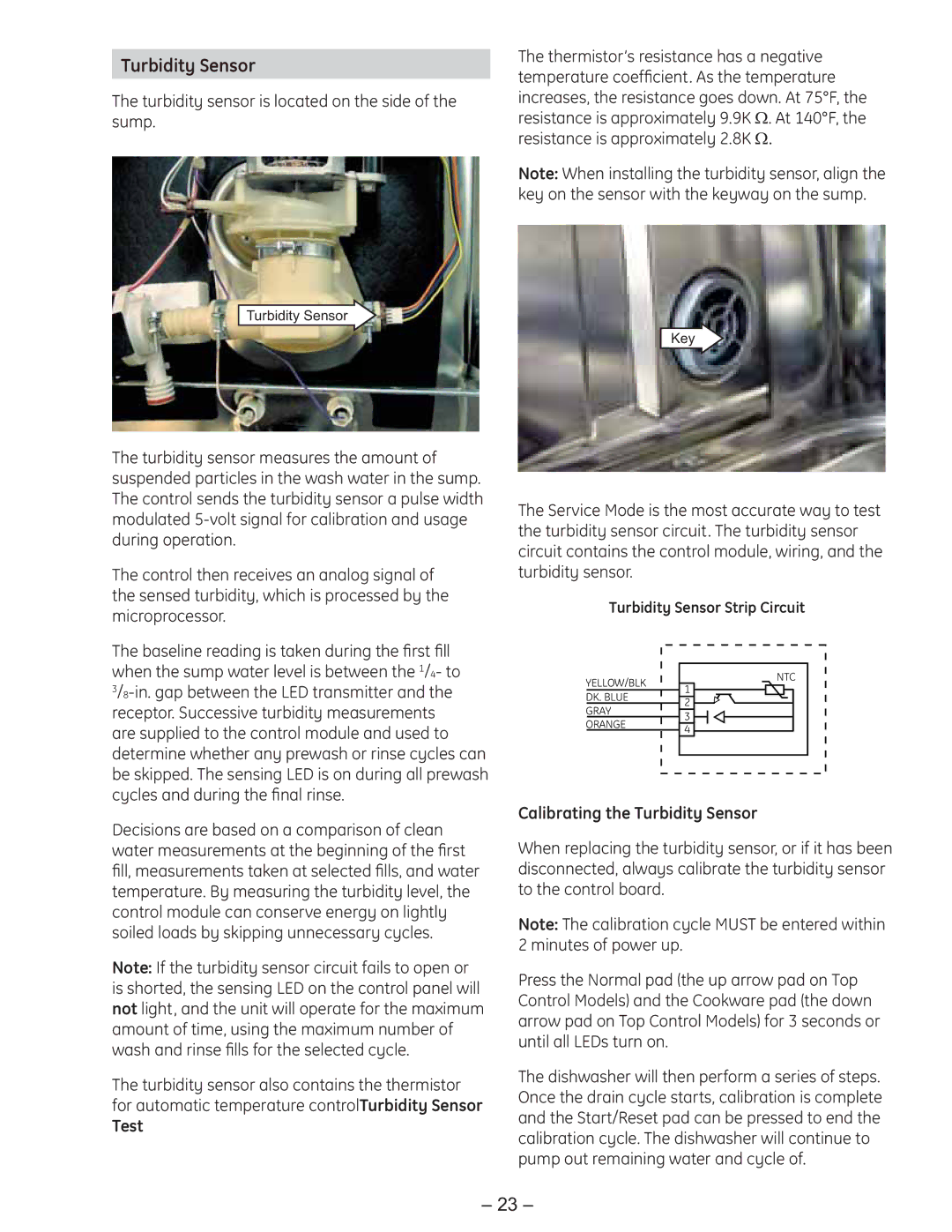
The turbidity sensor is located on the side of the sump.
Turbidity Sensor
The turbidity sensor measures the amount of suspended particles in the wash water in the sump. The control sends the turbidity sensor a pulse width modulated
The control then receives an analog signal of the sensed turbidity, which is processed by the microprocessor.
The baseline reading is taken during the first fill when the sump water level is between the 1/4- to
Decisions are based on a comparison of clean water measurements at the beginning of the first fill, measurements taken at selected fills, and water temperature. By measuring the turbidity level, the control module can conserve energy on lightly soiled loads by skipping unnecessary cycles.
Note: If the turbidity sensor circuit fails to open or is shorted, the sensing LED on the control panel will not light, and the unit will operate for the maximum amount of time, using the maximum number of wash and rinse fills for the selected cycle.
The turbidity sensor also contains the thermistor for automatic temperature controlTurbidity Sensor
Test
The thermistor’s resistance has a negative temperature coefficient. As the temperature increases, the resistance goes down. At 75°F, the resistance is approximately 9.9K Ω. At 140°F, the resistance is approximately 2.8K Ω.
Note: When installing the turbidity sensor, align the key on the sensor with the keyway on the sump.
Key
The Service Mode is the most accurate way to test the turbidity sensor circuit. The turbidity sensor circuit contains the control module, wiring, and the turbidity sensor.
Turbidity Sensor Strip Circuit
YELLOW/BLK | NTC | |
1 | ||
DK. BLUE | ||
2 | ||
GRAY | ||
3 | ||
ORANGE | ||
4 | ||
|
Calibrating the Turbidity Sensor
When replacing the turbidity sensor, or if it has been disconnected, always calibrate the turbidity sensor to the control board.
Note: The calibration cycle MUST be entered within 2 minutes of power up.
Press the Normal pad (the up arrow pad on Top Control Models) and the Cookware pad (the down arrow pad on Top Control Models) for 3 seconds or until all LEDs turn on.
The dishwasher will then perform a series of steps. Once the drain cycle starts, calibration is complete and the Start/Reset pad can be pressed to end the calibration cycle. The dishwasher will continue to pump out remaining water and cycle of.
– 23 –