Control Module
The door panel must be removed to access the control module. (See Door Panel.) The main control is considered a “smart” control, capable of learning the water temperature and turbidity characteristics of the home.
It is normal for the cycle times to vary over a period of time from the factory default settings due to temperature and water quality.
The control module is held in place by a single screw that secures the module to the right side of the inner door panel. (The screw is located on the outside of the inner door panel.)
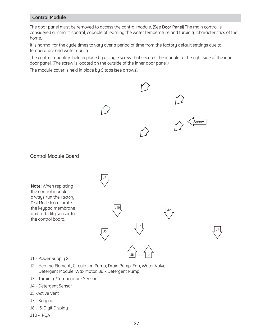
The module cover is held in place by 5 tabs (see arrows).
Screw
Control Module Board
Note: When replacing the control module, always run the Factory Test Mode to calibrate the keypad membrane and turbidity sensor to the control board.
J4
J10
J2
J7
J5
J1
J8 J3
J1 - Power Supply X
J2 - Heating Element, Circulation Pump, Drain Pump, Fan, Water Valve, Detergent Module, Wax Motor, Bulk Detergent Pump
J3 - Turbidity/Temperature Sensor
J4 - Detergent Sensor
J5
J7 - Keypad
J8 -
J10 - PQA
– 27 –