Installation Instructions

INSTALLATION—VENTED TO THE OUTSIDE

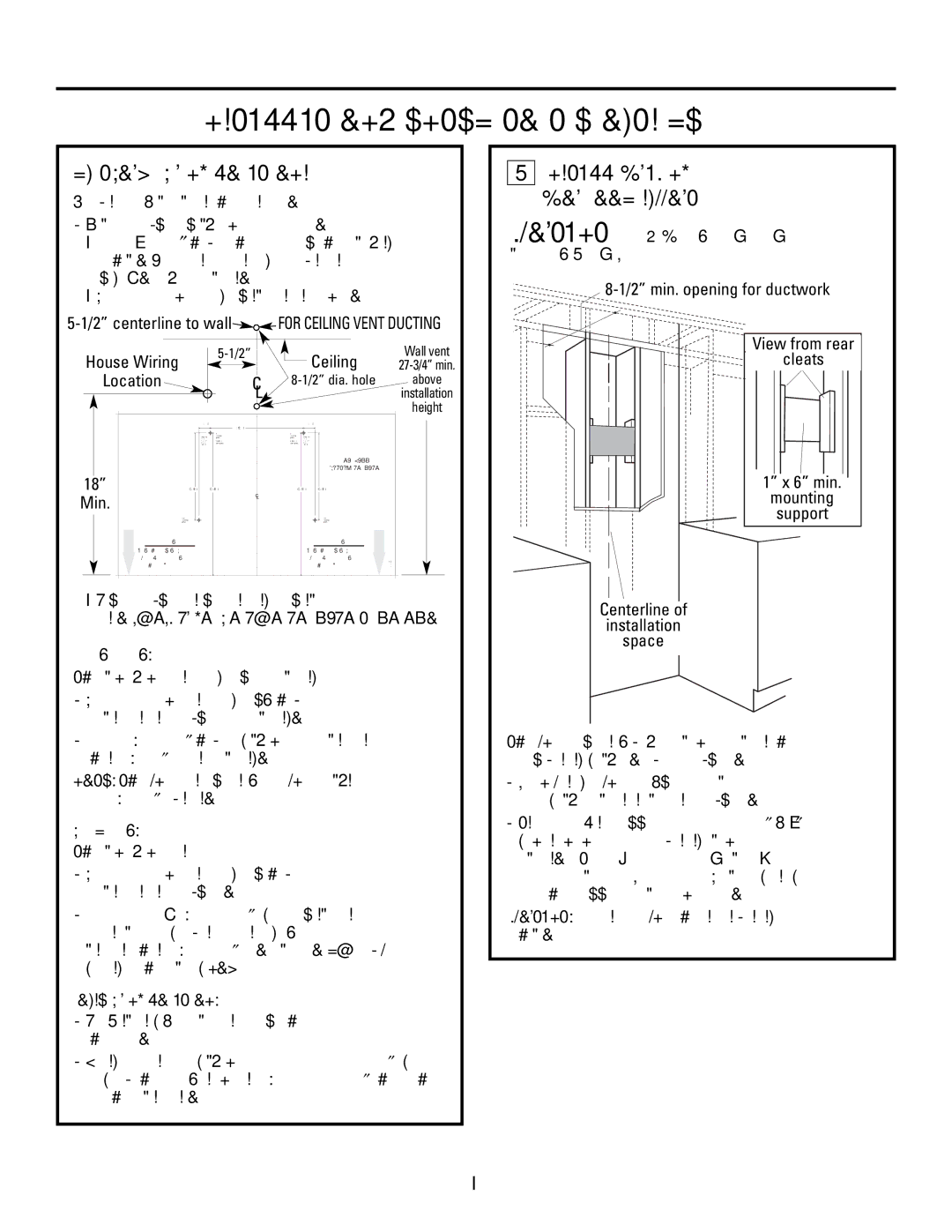
DUCTWORK, WIRING LOCATIONS

Determine the exact location of the vent hood.

Locate the template packed with the literature.

Measure 36from the floor to the top of the cooking surface. Add hood installation height determined on page 7. Mark that location.

Use a level to draw a straight pencil line on the wall.

5-1/2” centerline to wallFOR CEILING VENT DUCTING


5-1/2”


Wall vent


House Wiring


Ceiling


27-3/4” min.


Location


C


above


8-1/2” dia. hole


L


installation


height


1-1/4


1-1/4


10-1/16


REAR WALL


MOUNTING TEMPLATE


18”


9-7/16


15-7/16


15-7/16


9-7/16


Min.


C


L


Installation Height


Installation Height


Align Bottom Edge With


Align Bottom Edge With


Pencil Line Indicating


Pencil Line Indicating


Bottom of Hood


Bottom of Hood


Tape the template in position along the penciled line. CHECK TO BE SURE THE TEMPLATE IS LEVEL.

Ceiling ducting:

If ductwork will vent straight up to the ceiling:

Use a level to draw a line straight up, from the centerline on the template to the ceiling.

Measure 5-1/2from the back wall to the centerline of an 8-1/2hole on the ceiling.

NOTE: If drywall is not present, add drywall thickness to the 5-1/2dimension.

Wall Ducting:

If ductwork will vent to the rear:

Use a level to draw a line straight up from the centerline on the template.

Measure at least 27-3/4above the pencil line

that indicates the bottom installation height, to the centerline of an 8-1/2dia. duct hole. (Hole may be elongated for duct elbow.)

HOUSE WIRING LOCATION:

The junction box is located on the top left side of the hood.

Wiring should enter the back wall at least 18above the bottom of the hood, and within 5-1/2of the left side of the centerline.

1INSTALL FRAMING FOR HOOD SUPPORT

IMPORTANTFraming must be capable of supporting 100 lbs.

8-1/2” min. opening for ductwork

View from rear

cleats

1” x 6” min.

mounting

support

Centerline of

installation

space

If drywall is present, mark the screw hole locations for the top mounting brackets. Remove the template.

Cut away enough drywall to expose 2 vertical studs at the bracket location indicated on the template.

Install a horizontal support at least 1x 6between two wall studs at the mounting screw location. The horizontal support must be flush with the room side of the studs. Use cleats behind both sides of the support to secure to wall studs.

IMPORTANT: Reinstall drywall for an even mounting surface.

9

Page 9
Image 9
GE ZV830 manual INSTALLATION-VENTED to the Outside, DUCTWORK, Wiring Locations, Install Framing for Hood Support

ZV830 specifications

The GE ZV830 is a groundbreaking and sophisticated addition to the lineup of kitchen appliances, designed to elevate both functionality and aesthetics. Packed with a range of advanced features, the ZV830 stands out as a state-of-the-art microwave that not only meets but exceeds modern culinary demands.

One of the standout characteristics of the GE ZV830 is its sleek and modern design, which seamlessly integrates into any kitchen decor. The appliance features a stainless-steel finish that is not only visually appealing but also easy to clean, making it a practical choice for busy homeowners. The unit is designed for installation over a range or cooktop, freeing up counter space while providing powerful cooking capabilities.

The ZV830 is equipped with a robust 1.7 cubic feet capacity, providing ample space for cooking large dishes or multiple items simultaneously. This microwave offers an impressive 1,000 watts of cooking power, ensuring quick and efficient heating, defrosting, and cooking of food.

One of the key technologies implemented in the GE ZV830 is its sensor cooking feature. This advanced technology allows the microwave to automatically adjust cooking times and power levels based on the moisture released from the food. As a result, users can achieve perfectly cooked meals without the guesswork traditionally associated with microwave cooking.

Additionally, the GE ZV830 boasts a range of convenient cooking presets and auto-reheat options, streamlining meal preparation. Features such as popcorn settings and pizza reheating options make it a versatile tool for any kitchen. The unit also includes a dedicated steam function, which is perfect for health-conscious individuals looking to prepare steamed vegetables easily.

Highly regarded for its user-friendly interface, the GE ZV830 includes a large LED display that provides clear visibility of cooking settings and times. The straightforward keypad allows for easy input, making it accessible for all users, including those less familiar with kitchen technology.

Furthermore, the GE ZV830 is designed with safety in mind. It includes child lock features to prevent unintended use, offering peace of mind for families. In conclusion, the GE ZV830 is an exemplary microwave that combines design, performance, and innovative technology to enhance the cooking experience. Its advanced features and user-centric design make it a valuable addition to any modern kitchen.