ge.com

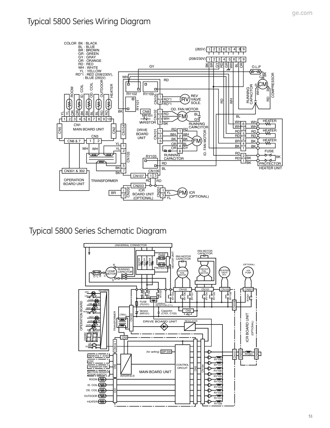
Typical 5800 Series Wiring Diagram


COLOR BK : BLACK


BL : BLUE


(265V)

1

2

3

6

5

4

8 9


BR : BROWN


GR : GREEN


GY : GRAY


(208/230V)

1

2

3

4

5

6

7

9


OR : ORANGE


BK BR

GY RD GR WH

BL OR


RD : RED


GY


O.L.P


WH : WHITE


YL : YELLOW


BK


RD*1 : RED (208/230V),


RY101

NR101CN102CN105

3

WH

FM


RD


WH


BL


RUNNING CAPACITOR WH


YL YL OR OR

BKID.COIL BK

BL BL

RDOUTDOOR RD HEATER


WH


C

RD COMPRESSOR


: BLUE (265V)


RD


ROOM


COIL OD.


RY102

RY109


REV.


S CM


R


1

RD*1


RV VALVE


3

RD*1


SOLE.


BK


CN8


1

OD. FAN MOTOR


RD


BL


1

2

3

4

5

6

7

8

9

10


VARISTOR

5


GY


WH


WH


HEATER


CN1


CN104


BK


RUNNING


6


WH

WH


CN5


CN2


CN6 & 7


1

2


YL


DRIVE

CN101

5

OR

3

BL

FM MOTOR


4


HEATER


BR

BK


MAIN BOARD UNIT


1

RD

1

RD CAPACITOR


RD

3

RD


CN3


BOARD


3

WH

2

WH


RD

5

RD


UNIT


BK


BK


2


HEATER


WH


WH


YL 2


OR 6 GY

FAN


1


FUSE


1

CN103


4


BK


BK


CAPACITOR

ID.


RD

1

BK


RY103


RUNNING


RD

2


BK


5


RD


BK

PROTECTOR


BK


BL


HEATER UNIT

CN301 & 302


BK

7


CN106


CN107

1


3


OPERATION

TRANSFORMER


RD


RD


BOARD UNIT


CN202

CN203


CN201


BR

2


3 YL

PM ICR


BOARD UNIT


1


ICR


1


(OPTIONAL)


YL


(OPTIONAL)


Typical 5800 Series Schematic Diagram


UNIVERSAL CONNECTOR


UNIT

FAN MOTOR

FAN MOTOR


FUSE

CAPACITOR


HEATER

HEATER

HEATER


HEATER

CAPACITOR


R


(OPTIONAL)


RUNNING


PROTECTOR


INDOOR

REVERSE

ICR


COMP.


OUTDOOR


CAPACITOR


FAN


MOTOR


FAN

MOTOR

VALVE

PUMP

O. L. P.

C


MOTOR


SOL.


S


DECODER


RY109

RY102

RY101


CN102


CN101

CN105


CN201


OPE


RY103

RY106

RY107

RY104

RY105

RY108


RY201


OPE


COOL


OPERATION BOARD

FAN


FUSE

CURRENT


CN106


(FU101)


DETECTOR (CT1)


HEAT


MODE


7 TRANSFORMER


Varistor

Capacitor

CN8


(TR1)

CN103

(NR101)

(C101, C102)


ICR BOARD UNIT (OPTIONAL)


HIGH


LOW


DRIVE BOARD UNIT

REGULATOR


AUTO


FAN SPEED


THERMO


CN3


UP


&


DOWN


CN6


(for setting)

DIP SW


CN107

CN203

RY201

CN202


REMOTE T' STAT


RY108


CDC


TRANSFER FAN

CN5


CONTROL

CN2

CN104

RY107


CIRCUIT


RY106


MOTION SENSOR


MAIN BOARD UNIT


DOOR SWITCH


INTERFACE


RY105


ROOM


RY104


ID. COIL


RY103


CN1

OD. COIL

RY102


OUTDOOR


RY101


HEATER


RY109


51

Page 51
Image 51
GE Monogram 3900 Series, 2900 Series manual Typical 5800 Series Schematic Diagram, Typical 5800 Series Wiring Diagram

3900 Series, 2900 Series, 5800 Series specifications

The GE Monogram series is renowned for its commitment to excellence in kitchen appliances, offering high-end features, superior technology, and outstanding performance. Among the extensive lineup, the 3900 Series, 2900 Series, and 5800 Series stand out for their innovative designs and multifunctionality.

The GE Monogram 3900 Series is a flagship line that combines luxury with practicality. It features stainless steel construction for durability and elegance, along with a commercial-grade appearance that enhances any kitchen setting. One of its key characteristics is the advanced convection cooking technology, which ensures even heat distribution for perfectly cooked dishes. This series often includes options like dual-fuel ranges that provide the precision of a gas cooktop and the reliable performance of an electric oven. Smart technology integration allows users to control their appliances remotely, making meal preparation more convenient.

The 2900 Series presents a compelling option for those seeking high performance in a more compact form factor. This series is characterized by its sleek design and versatile capabilities, making it ideal for urban homes or smaller kitchens. The ovens typically feature multiple cooking modes, including a self-cleaning function and steam cooking options, which preserve nutrients in food while ensuring moist results. Energy efficiency is a priority in this series, with many units designed to reduce consumption without sacrificing power or performance.

On the other hand, the GE Monogram 5800 Series is designed for those who desire the pinnacle of culinary technology. With features like a dual-fuel convection oven and integrated temperature probes, home chefs can achieve restaurant-quality results. The 5800 Series boasts a variety of customizable settings that enable precision cooking, while the built-in smart technologies provide remote monitoring and alerts. The design integrates seamlessly with contemporary kitchens, featuring intuitive touch controls and high-quality finishes that reflect sophistication.

Each of these series embodies GE’s commitment to crafting appliances that inspire both culinary creativity and efficient cooking. With the Monogram brand, customers enjoy a blend of elegance, performance, and smart technology that makes preparing meals an effortless and enjoyable experience. Whether you choose the 3900, 2900, or 5800 Series, you’re investing in an appliance that brings professional-grade quality to your home kitchen.