This manual should remain with the unit
Air-cooled Recreational Vehicle Generators
Model QUIETPACT 40G
GENERA OHVI
CONTENTS
AUTHORIZED SERVICE DEALER LOCATION
OPERATION AND MAINTENANCE
HOW TO OBTAIN SERVICE
Safety Rules
Part II - Installation Instructions
Adjustments
Exploded Views and Parts Lists
Despite the safe design of this generator
GENERAL HAZARDS
Parts of the generator are rotating and/or hot
during operation. Exercise care near running generators
ELECTRICAL HAZARDS
FIRE HAZARDS
EXPLOSION HAZARDS
Model 004700-0 - QUIETPACT 40G
1.1 GENERATOR IDENTIFICATION
Model Number
kW Rating
1.5 SPECIFICATIONS
1.3 SAFETY
Do not overload the generator. Some installa
1.2 GENERATOR APPLICABILITY
1.5.5 GENERATOR
Generac does not recommend using any
1.5.2 FUEL CONSUMPTION
1.5.3 ENGINE OIL REQUIREMENTS
2.4.1 INSTALLATION
2.1.2 START/STOP SWITCH
2.1 GENERATOR CONTROL PANEL
2.2 OPTIONAL REMOTE START/STOP PANEL
2.4.2 ENGINE LUBRICATION
2.5 STARTING THE GENERATOR
2.4.3 FUEL SUPPLY
2.4.4 COOLING AND VENTILATING AIR
2.9.2 HIGH TEMPERATURE SWITCH
2.9.1 LOW OIL PRESSURE SWITCH
Figure 2.2 - Low Oil Pressure and High Temperature Switches
2.6 STOPPING THE GENERATOR
2.9.3 FIELD BOOST
2.10 ADDITIONAL INFORMATION
2.10.1 25-HOUR BREAK-IN PERIOD
2.9.4 OVERVOLTAGE PROTECTION
3.1 CHECKING THE ENGINE OIL LEVEL
Figure 3.1 - Oil Maintenance Features
3.2 CHANGING THE ENGINE OIL AND/OR OIL FILTER
2.10.4 OPERATION IN HIGH GRASS OR BRUSH
3.3.1 CLEANING THE FOAM PRECLEANER
3.3 MAINTAINING THE ENGINE AIR CLEANER
Figure 3.2 - Engine Air Cleaner
3.3.2 CLEANING OR REPLACING THE PAPER FILTER
3.7 CLEAN SPARK ARRESTOR
3.4 CLEAN AIR INTAKE
Figure 3.3 - Cleaning Air Intake
Figure 3.4 - Setting the Spark Plug Gap
3.9 BATTERY MAINTENANCE
3.8 CLEANING THE GENERATOR
Do NOT use a forceful spray of water to clean
Use tools with insulated handles Wear rubber gloves and boots
3.13 ADJUSTING VALVE CLEARANCE
3.12 OUT OF SERVICE PROCEDURE
3.12.1 REMOVAL FROM SERVICE
3.12.2 RETURN TO SERVICE
Figure 3.8 - Tightening Jam Nut
3.14 RV GENERATOR SERVICE INTERVAL
SHOULD ATTEMPT INSTALLATION
INSTALLATION INSTRUCTIONS
PART
ONLY QUALIFIED ELECTRICIANS OR CONTRACTORS
NOTICE TO INSTALLER
FIRE HAZARDS
1.1 PURPOSE AND SCOPE OF THE MANUAL
1.2 SAFETY
1.4 EQUIPMENT DESCRIPTION
1.5 GENERATOR ENGINE OPERATING SPEED
VIEW FROM TOP
Major Features
2.1.1 GENERATOR LOCATION
2.1 LOCATION AND SUPPORT
2.1.2 GENERATOR SUPPORT
2.1.3 SUSPENDED MOUNTING
2.1.4 GENERATOR RESTRAINT
2.2 GENERATOR COMPARTMENTS
2.2.2 COMPARTMENT CONSTRUCTION
2.2.1 COMPARTMENT SIZE
2.2.4 ACOUSTICS
2.2.3 SOUND INSULATING MATERIALS
Figure 2.6 - Types of Lock Seams
Figure 2.8 - Compartment Floor Cutout Drawing 0D8716-C
Figure 2.7 - Typical Noise Abatement 2.2.5 COMPARTMENT FLOOR CUTOUTS
VIEW FROM TOP
All measurements are in millimeters, 25.4 mm = 1”
2.3 COOLING AND VENTILATING AIR
2.3.2 TESTING THE INSTALLATION
2.4 GASOLINE FUEL SYSTEM
2.3.1 GENERATOR AIRFLOW
2.4.1 FUEL TANK
2.5 EXHAUST SYSTEM
2.4.2.2 Flexible Fuel Line
2.4.2 GENERATOR FUEL SUPPLY LINE 2.4.2.1 Rigid Fuel Lines
Figure 2.12 - Spark Arrestor Installation
2.5.2 EXHAUST SYSTEM SAFETY
2.6 ELECTRICAL CONNECTIONS
2.5.1 SPARK ARRESTOR
2.6.1 ELECTRICAL JUNCTION BOX
2.6.2 WIRING
2.6.3 GENERATOR AC CONNECTIONS
2.6.4 CONDUIT
2.6.5 ISOLATING DIFFERENT POWER SOURCES
2.6.6 POWER SUPPLY CORD
Figure 2.14 - Transfer Switch Isolation Method
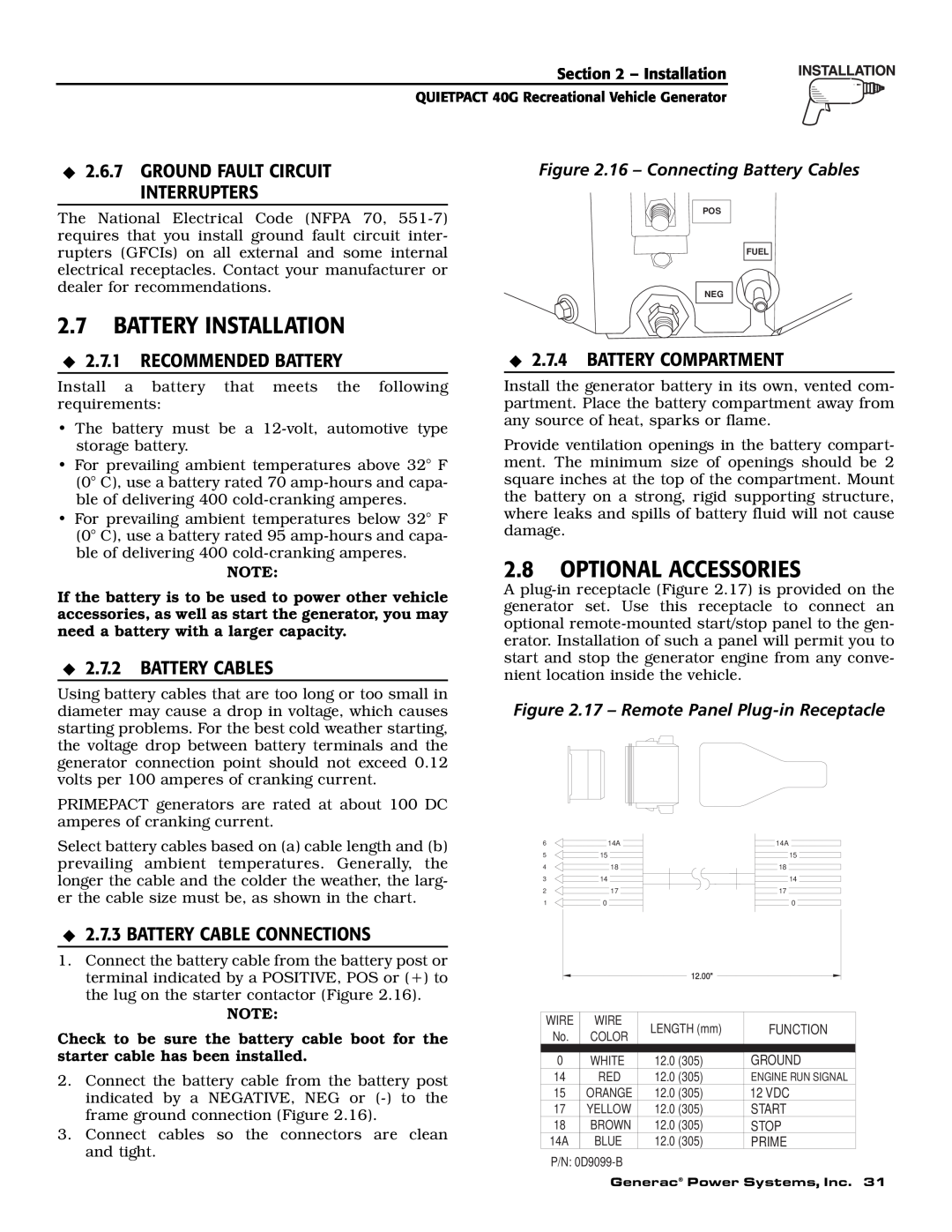
2.8 OPTIONAL ACCESSORIES
2.7 BATTERY INSTALLATION
2.7.1 RECOMMENDED BATTERY
2.7.2 BATTERY CABLES
3.4 TESTING UNDER LOAD
3.1 POST INSTALLATION TESTS
Do not make any unnecessary adjustments
3.2 BEFORE INITIAL START-UP
3.5 INSTALLATION CHECKLIST
34 Generac Power Systems, Inc
Appendix 1 - Notes
PROBLEM
TROUBLESHOOTING GUIDE
CAUSE
CORRECTION
Appendix 3 - Electrical Data
36 Generac Power Systems, Inc
BROWN
Power
Data
QUIETPACT
Appendix 3 - Electrical
Appendix 4 - Exploded Views and Parts Lists
38 Generac Power Systems, Inc
Enclosure - Drawing No. 0D8352-E
TO CARB
Appendix 4 - Exploded Views and Parts Lists
PART NO. QTY
DESCRIPTION
40 Generac Power Systems, Inc
DESCRIPTION
25 24
42 Generac Power Systems, Inc
DESCRIPTION
44 Generac Power Systems, Inc
BOOT CHOKE SOLENOID PLASTIC
ASSEMBLY BRACKET GOVERNOR
ASSEMBLY, GOVERNOR LEVER
GASKET CARBURETOR/MANIFOLD
46 Generac Power Systems, Inc
SCREW, HHFC M8-1.25 X 35MM
TAPERED CRANKSHAFT ASSEMBLY
VALVE SPRING WEAR WASHER
OIL PRESSURE RELIEF COVER
YOUR WARRANTY RIGHTS AND OBLIGATIONS
CALIFORNIA AND FEDERAL EMISSION CONTROL WARRANTY STATEMENT
MANUFACTURER’S EMISSION CONTROL SYSTEM WARRANTY COVERAGE
PURCHASER’S/OWNER’S WARRANTY RESPONSIBILITIES
EMISSION RELATED PARTS INCLUDE THE FOLLOWING
EMISSION CONTROL SYSTEM WARRANTY
1 Utility 2 Lawn and Garden Equipment
3 Recreational Vehicle RV Generator 4 Industrial Mobile IM Generator
WARRANTY SCHEDULE - COMMERCIAL APPLICATIONS
GENERAC POWER SYSTEMS’ THREE-YEAR LIMITED WARRANTY
WARRANTY SCHEDULE - CONSUMER/PERSONAL APPLICATIONS
GENERAC POWER SYSTEMS, INC