English
![]() Warning: The Rip Fence must be parallel with the Saw Blade in order to prevent Kickback when rip cutting.
Warning: The Rip Fence must be parallel with the Saw Blade in order to prevent Kickback when rip cutting.
RIP FENCE ADJUSTMENT
![]() Warning: To prevent personal Injury, always unplug the saw from power source before make any adjustments.
Warning: To prevent personal Injury, always unplug the saw from power source before make any adjustments.
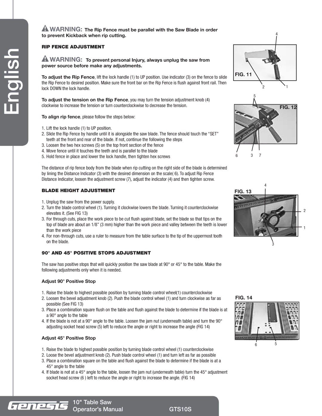
To adjust the Rip Fence, lift the lock handle (1) to UP position. Use indicator (3) on the fence to slide the Rip Fence to desired position. Make sure the front bar on the Rip Fence is flush against front rail. Then lock DOWN the lock handle.
To adjust the tension on the Rip Fence, you may turn the tension adjustment knob (4) clockwise to increase the tension or turn counterclockwise to decrease the tension.
To align rip fence, please follow the steps below:
1.Lift the lock handle (1) to UP position.
2.Slide the Rip Fence by handle until it is alongside the saw blade. The fence should touch the “SET” teeth at the front and rear of the blade. If not, continue the following the steps
3.Loosen the two hex screws (5) on the top front section of the fence
4.Move fence until it touches the teeth and is parallel to the blade
5.Hold fence in place and lower the lock handle, then tighten hex screws
The distance of rip fence body from the blade when rip cutting on the right side of the blade is determined by lining the Distance Indicator (3) with the desired dimension on the scale( 6). To adjust Rip Fence Distance Indicator, loosen the adjustment screw (7), adjust the indicator (4) and then tighten screw.
BLADE HEIGHT ADJUSTMENT
1.Unplug the saw from the power supply.
2.Turn the blade control wheel (1). Turning it clockwise lowers the blade. Turning it counterclockwise elevates it. (See FIG 13)
3.For through cuts, place the work piece to be cut flush against blade, set the blade so that tips on the top of blade are about an 1/8” (3 mm) higher than the work piece and valley between the teeth is lower than the work piece
4.For
90° AND 45° POSITIVE STOPS ADJUSTMENT
The saw has positive stops that will quickly position the saw blade at 90° or 45° to the table. Make the following adjustments only when it is needed.
Adjust 90° Positive Stop
1.Raise the blade to highest possible position by turning blade control wheel(1) counterclockwise
2.Loosen the bevel adjustment knob (2). Push the blade control wheel (1) and turn clockwise as far as possible (See FIG 13)
3.Place a combination square flush on the table and flush against the blade to determine if the blade is at a 90° angle to the table
4.If the blade is not at a 90° angle to the table. Loosen the jam nut (underneath table) and turn the 90° adjusting socket head screw (5) left to reduce the angle or right to increase the angle (FIG 14)
Adjust 45° Positive Stop
1.Raise the blade to highest possible position by turning blade control wheel (1) counterclockwise
2.Loose the bevel adjustment knob (2). Push blade control wheel (1) and turn left as far as possible
3.Place a combination square on the table and flush against the blade to determine if the blade is at a 45° angle to the table
4.If blade is not at a 45° angle to the table, loosen the jam nut (underneath table) turn the 45° adjustment socket head screw (6 ) left to reduce the angle or right to increase the angle. (FIG 14)
4
FIG. 11
21
5
FIG. 12
6 | 3 | 7 |
4
FIG. 13
2
1
3
FIG. 14
65
10" Table Saw |
|
Operator’s Manual | GTS10S |