ASSEMBLING THE BLADE CONTROL WHEEL HANDLE
English
Tighten the screw through the wheel handle 4 onto the blade control wheel.
![]() Warning: To prevent personal Injury, always unplug the saw from power source before make any adjustments.
Warning: To prevent personal Injury, always unplug the saw from power source before make any adjustments.
BLADE GUARD ASSEMBLY INSTALLATION
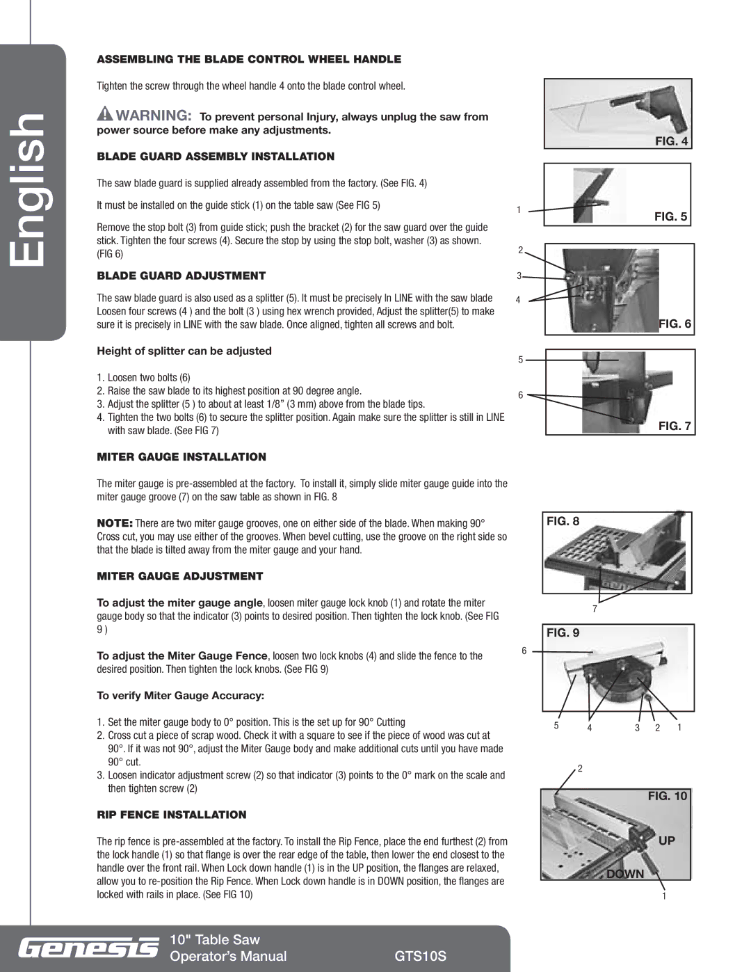
The saw blade guard is supplied already assembled from the factory. (See FIG. 4)
It must be installed on the guide stick (1) on the table saw (See FIG 5)
Remove the stop bolt (3) from guide stick; push the bracket (2) for the saw guard over the guide stick. Tighten the four screws (4). Secure the stop by using the stop bolt, washer (3) as shown. (FIG 6)
BLADE GUARD ADJUSTMENT
The saw blade guard is also used as a splitter (5). It must be precisely In LINE with the saw blade Loosen four screws (4 ) and the bolt (3 ) using hex wrench provided, Adjust the splitter(5) to make sure it is precisely in LINE with the saw blade. Once aligned, tighten all screws and bolt.
Height of splitter can be adjusted
1.Loosen two bolts (6)
2.Raise the saw blade to its highest position at 90 degree angle.
3.Adjust the splitter (5 ) to about at least 1/8” (3 mm) above from the blade tips.
4.Tighten the two bolts (6) to secure the splitter position. Again make sure the splitter is still in LINE with saw blade. (See FIG 7)
MITER GAUGE INSTALLATION
FIG. 4
1 | FIG. 5 |
|
2
3 ![]()
4
FIG. 6
5
6
FIG. 7
The miter gauge is
NOTE: There are two miter gauge grooves, one on either side of the blade. When making 90° Cross cut, you may use either of the grooves. When bevel cutting, use the groove on the right side so that the blade is tilted away from the miter gauge and your hand.
MITER GAUGE ADJUSTMENT
To adjust the miter gauge angle, loosen miter gauge lock knob (1) and rotate the miter gauge body so that the indicator (3) points to desired position. Then tighten the lock knob. (See FIG 9 )
To adjust the Miter Gauge Fence, loosen two lock knobs (4) and slide the fence to the | 6 |
| |
desired position. Then tighten the lock knobs. (See FIG 9) |
|
To verify Miter Gauge Accuracy: |
|
1.Set the miter gauge body to 0° position. This is the set up for 90° Cutting
2.Cross cut a piece of scrap wood. Check it with a square to see if the piece of wood was cut at 90°. If it was not 90°, adjust the Miter Gauge body and make additional cuts until you have made 90° cut.
3.Loosen indicator adjustment screw (2) so that indicator (3) points to the 0° mark on the scale and then tighten screw (2)
RIP FENCE INSTALLATION
The rip fence is
FIG. 8
7
FIG. 9
5 | 4 | 3 | 2 | 1 |
2
FIG. 10
UP
DOWN
1
10" Table Saw |
|
Operator’s Manual | GTS10S |