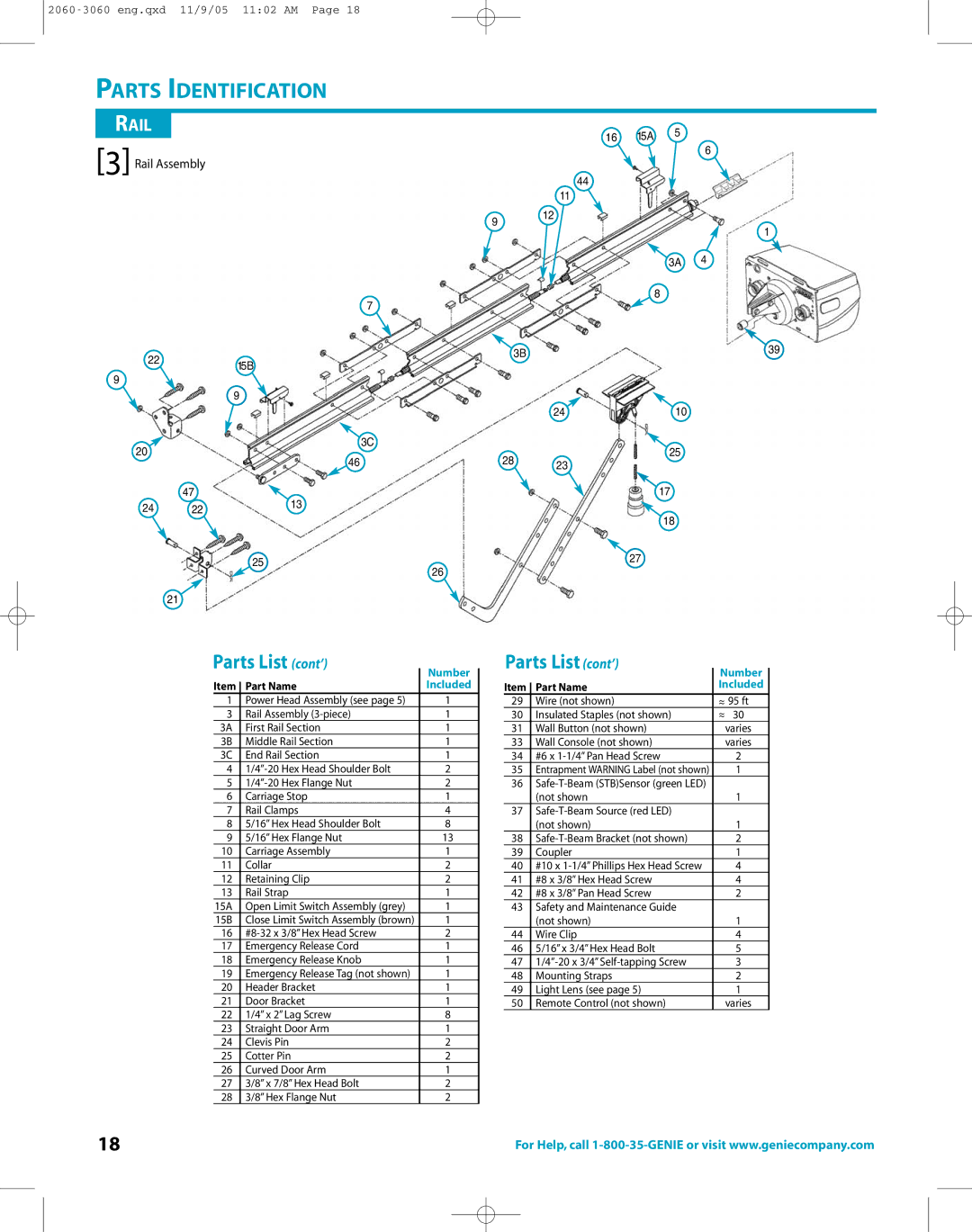
PARTS IDENTIFICATION
RAIL |
|
|
| 16 | 15A | 5 |
|
[3] Rail Assembly |
|
|
| 6 | |||
|
|
|
|
| |||
|
| 44 |
|
|
| ||
|
|
|
|
|
|
| |
|
|
|
| 11 |
|
|
|
|
|
| 9 | 12 |
|
|
|
|
|
|
|
|
| 1 | |
|
|
|
|
|
|
| |
|
|
|
|
|
| 3A | 4 |
|
|
| 7 |
|
| 8 |
|
|
|
|
|
|
|
| |
22 |
|
| 3B |
|
|
| 39 |
| 15B |
|
|
|
| ||
|
|
|
|
|
| ||
|
|
|
|
|
|
| |
9 |
|
|
|
|
|
|
|
|
| 9 |
|
|
|
|
|
|
|
|
| 24 |
| 10 |
|
20 |
|
| 3C |
|
| 25 |
|
| 46 | 28 |
|
|
| ||
|
| 23 |
|
|
| ||
| 47 | 13 |
|
|
| 17 |
|
24 | 22 |
|
|
|
|
| |
|
|
|
| 18 |
| ||
|
|
|
|
|
|
| |
25 | 27 | |
26 | ||
| ||
21 |
|
Parts List (cont’) |
| Number |
| ||
|
| ||||
|
|
|
|
| |
Item |
| Part Name |
| Included |
|
|
|
| |||
1 |
| Power Head Assembly (see page 5) |
| 1 |
|
3 |
| Rail Assembly |
| 1 |
|
3A |
| First Rail Section |
| 1 |
|
3B |
| Middle Rail Section |
| 1 |
|
3C |
| End Rail Section |
| 1 |
|
4 |
|
| 2 |
| |
5 |
|
| 2 |
| |
6 |
| Carriage Stop |
| 1 |
|
7 |
| Rail Clamps |
| 4 |
|
8 |
| 5/16” Hex Head Shoulder Bolt |
| 8 |
|
9 |
| 5/16” Hex Flange Nut |
| 13 |
|
10 |
| Carriage Assembly |
| 1 |
|
11 |
| Collar |
| 2 |
|
12 |
| Retaining Clip |
| 2 |
|
13 |
| Rail Strap |
| 1 |
|
15A |
| Open Limit Switch Assembly (grey) |
| 1 |
|
15B |
| Close Limit Switch Assembly (brown) |
| 1 |
|
16 |
|
| 2 |
| |
17 |
| Emergency Release Cord |
| 1 |
|
18 |
| Emergency Release Knob |
| 1 |
|
19 |
| Emergency Release Tag (not shown) |
| 1 |
|
20 |
| Header Bracket |
| 1 |
|
21 |
| Door Bracket |
| 1 |
|
22 |
| 1/4” x 2” Lag Screw |
| 8 |
|
23 |
| Straight Door Arm |
| 1 |
|
24 |
| Clevis Pin |
| 2 |
|
25 |
| Cotter Pin |
| 2 |
|
26 |
| Curved Door Arm |
| 1 |
|
27 |
| 3/8” x 7/8” Hex Head Bolt |
| 2 |
|
28 |
| 3/8” Hex Flange Nut |
| 2 |
|
Parts List (cont’) |
| Number |
| ||
|
| ||||
|
|
|
|
| |
Item |
| Part Name |
| Included |
|
|
|
| |||
29 |
| Wire (not shown) |
| ~ 95 ft |
|
30 |
| Insulated Staples (not shown) |
| ~ 30 |
|
31 |
| Wall Button (not shown) |
| varies |
|
33 |
| Wall Console (not shown) |
| varies |
|
34 |
| #6 x |
| 2 |
|
35 |
| Entrapment WARNING Label (not shown) |
| 1 |
|
36 |
|
|
|
| |
|
| (not shown |
| 1 |
|
37 |
|
|
|
| |
|
| (not shown) |
| 1 |
|
38 |
|
| 2 |
| |
39 |
| Coupler |
| 1 |
|
40 |
| #10 x |
| 4 |
|
41 |
| #8 x 3/8” Hex Head Screw |
| 4 |
|
42 |
| #8 x 3/8” Pan Head Screw |
| 2 |
|
43 |
| Safety and Maintenance Guide |
|
|
|
|
| (not shown) |
| 1 |
|
44 |
| Wire Clip |
| 4 |
|
46 |
| 5/16” x 3/4” Hex Head Bolt |
| 5 |
|
47 |
|
| 3 |
| |
48 |
| Mounting Straps |
| 2 |
|
49 |
| Light Lens (see page 5) |
| 1 |
|
50 |
| Remote Control (not shown) |
| varies |
|
18 | For Help, call |
