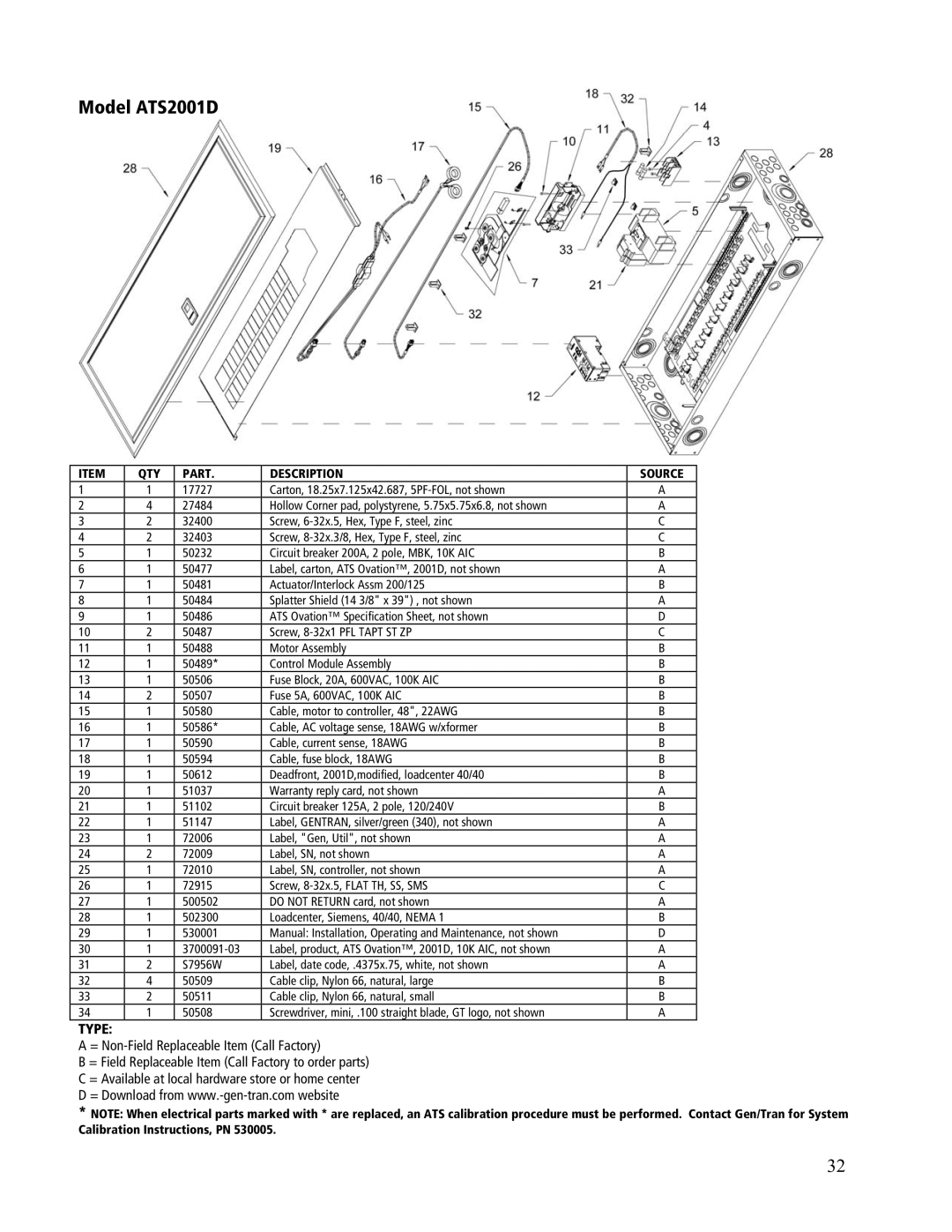
Model ATS2001D
ITEM | QTY | PART. | DESCRIPTION | SOURCE |
1 | 1 | 17727 | Carton, 18.25x7.125x42.687, | A |
2 | 4 | 27484 | Hollow Corner pad, polystyrene, 5.75x5.75x6.8, not shown | A |
3 | 2 | 32400 | Screw, | C |
4 | 2 | 32403 | Screw, | C |
5 | 1 | 50232 | Circuit breaker 200A, 2 pole, MBK, 10K AIC | B |
6 | 1 | 50477 | Label, carton, ATS Ovation™, 2001D, not shown | A |
7 | 1 | 50481 | Actuator/Interlock Assm 200/125 | B |
8 | 1 | 50484 | Splatter Shield (14 3/8" x 39") , not shown | A |
9 | 1 | 50486 | ATS Ovation™ Specification Sheet, not shown | D |
10 | 2 | 50487 | Screw, | C |
11 | 1 | 50488 | Motor Assembly | B |
12 | 1 | 50489* | Control Module Assembly | B |
13 | 1 | 50506 | Fuse Block, 20A, 600VAC, 100K AIC | B |
14 | 2 | 50507 | Fuse 5A, 600VAC, 100K AIC | B |
15 | 1 | 50580 | Cable, motor to controller, 48", 22AWG | B |
16 | 1 | 50586* | Cable, AC voltage sense, 18AWG w/xformer | B |
17 | 1 | 50590 | Cable, current sense, 18AWG | B |
18 | 1 | 50594 | Cable, fuse block, 18AWG | B |
19 | 1 | 50612 | Deadfront, 2001D,modified, loadcenter 40/40 | B |
20 | 1 | 51037 | Warranty reply card, not shown | A |
21 | 1 | 51102 | Circuit breaker 125A, 2 pole, 120/240V | B |
22 | 1 | 51147 | Label, GENTRAN, silver/green (340), not shown | A |
23 | 1 | 72006 | Label, "Gen, Util", not shown | A |
24 | 2 | 72009 | Label, SN, not shown | A |
25 | 1 | 72010 | Label, SN, controller, not shown | A |
26 | 1 | 72915 | Screw, | C |
27 | 1 | 500502 | DO NOT RETURN card, not shown | A |
28 | 1 | 502300 | Loadcenter, Siemens, 40/40, NEMA 1 | B |
29 | 1 | 530001 | Manual: Installation, Operating and Maintenance, not shown | D |
30 | 1 | Label, product, ATS Ovation™, 2001D, 10K AIC, not shown | A | |
31 | 2 | S7956W | Label, date code, .4375x.75, white, not shown | A |
32 | 4 | 50509 | Cable clip, Nylon 66, natural, large | B |
33 | 2 | 50511 | Cable clip, Nylon 66, natural, small | B |
34 | 1 | 50508 | Screwdriver, mini, .100 straight blade, GT logo, not shown | A |
TYPE:
A =
B = Field Replaceable Item (Call Factory to order parts)
C = Available at local hardware store or home center
D = Download from
*NOTE: When electrical parts marked with * are replaced, an ATS calibration procedure must be performed. Contact Gen/Tran for System Calibration Instructions, PN 530005.
32
