Manuals
/
Gigabyte
/
Computer Equipment
/
Personal Computer
Gigabyte
GS-R12T4H2-RH
manual
System Management
Models:
GS-R12T4H2-RH
1
75
81
81
Download
81 pages
60.98 Kb
72
73
74
75
76
77
78
79
Specification
Install
System Block Diagram
Password
QPI Error Report
Front Panel LED Indicator
Processor Configuration
Boot -time Diagnostic Screen
Bios Setup
Connector Icon Description
Page 75
Image 75
GS-R12T4H2-RH
Rack Mount Server
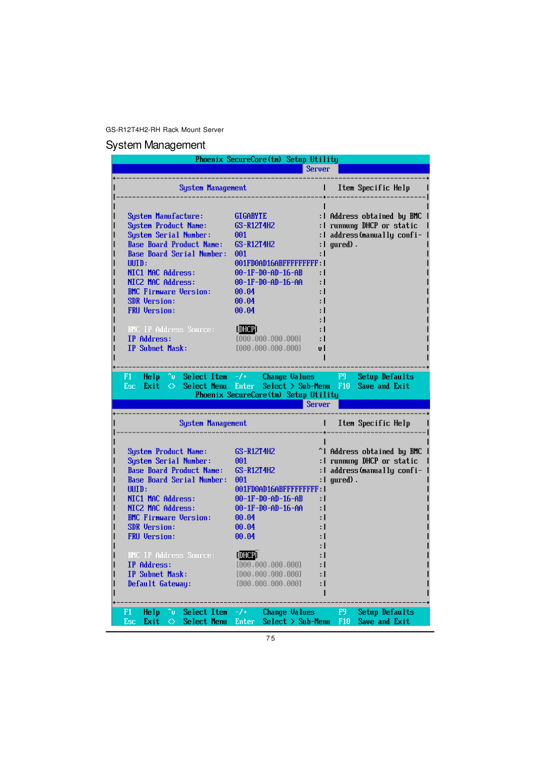
System Management
7 5
Page 74
Page 76
Page 75
Image 75
Page 74
Page 76
Contents
Service Guide
Preface
Table of Contents
Power Security Server
Precaution for Product with Laser Devices
Important safety information
FCC part 68 applicable to products fitted with USA modems
Federal Communications Commission FCC Statement
Canadian Department of Communications Compliance Statement
Class a equipment
System Specification
Super I/O
System Hardware Installation
Remove the chassis cover
Installing the Processor
Installing the Heat Sink
Installing the Memeory Module
7 6
1716 1 5
Code
Channel a Channel B Channel C
Dimm Population Table
Quad-Rank Single-Rank Dual-Rank
Installing the PCI Expansion Card
GS-R12T4H2-RH Rack Mount Server
Installing the Hard Disk Drive
HDD Security Lock
Installing and Replacing the FAN Duct
Replacing the FAN Assemblly
Replacing the Motherboard
Replacing the Power Supply
GS-R12T4H2-RH Rack Mount Server
Replacing the Chassis Cover
Front View of GS-R12T4H2-RH
Appearance of GS-R12T4H2-RH
Rear View of GS-R12T4H2-RH
Indicator Color State Description
Front Panel LED Indicator
LAN1
LAN port LED Indicator
Hard Disk Drive LED Description
Description SAS/SATA HDD indicator Green Red
Code Description
GC-BS14U-RH Back plane board Components
Intel ICH10R
System Block Diagram
Suggest Icon Description
Connector Icon Description
GA-7TTSE-RH Motherboard Component
Motherboard Placement and Jumper Setting
Item Component
Jumper Setting
BIOSRVCR1 Bios Revocery jumper
CLRCMOS1 Clear Cmos jumper
CLRRTC1 Clear RTC jumper
Meenable BMC Selection jumper
PASSDIS1 Skip Supervisor password jumper
JPSTRAP2/ JPSTRAP8 PilotII firmware upgrade jumper
Expansion Card Components Description
Bios Setup
MainMenu
Status Page Setup Menu / Option Page Setup Menu
Power
Boot
Processor Information
BIOSInformantion
System Date
System Time
TotalMemory
Advanced
Processor Configuration
Intel R Virtualization Technology
Processor Configuration
Multiprocessor Specification
Execute Disable Bit
EchoTPR
Machine Checking
Fast String Operations
SetMaxExtCPUID=3
Processor Power Management
Eist GV3 & C State
EISTPSDFunction
Osacpi C3 Report
TurboMode
State
CPU C State
CPU C7 Report
Package C State Limit
Acpi Mwait extensions
Memory Configuration
Rank Interleave setting
Memory Control Settings
Memory RAS Mode
Change Interleave setting
Advanced Chipset Configuration
1 Intel VT for Directed I/O VT-d
PassThrough DMA
Intel VT forDirected I/O VT-d
InterruptRemapping
Coherency Support
MemoryECCErrorLog
QPI Control Settings
QPI Link Fast Mode
QPI Error Report
LAN1OptionROM
PCI Configuration
Onboard LAN iSCSI Boot ROM
Onboard LAN1 Control
Legacy USB Support
LAN2OptionROM
Sata Configuration
Sata Configuration
Sata Port 0/1/2/3/4/5
Serial ATA
Multi-Sector Transfer
DeviceConfiguration
Serial Port a
Serial Port B
GS-R12T4H2-RH Rack Mount Server
Boot DeviceConfiguration
Boot -time Diagnostic Screen
Post Error Pause
NumLock
Thermal and Acoustic Configuration
Temperature hysteresis
Temperature guardband
Close loop Thermal Throttle
After Power Failure
Power
Security
Set Supervisor Password
Password on boot
Set User Password
Server
System Management
BMC IPAddress Source
System Management
Baud Rate
Console Redirection
Console Redirection
FlowControl
Continue C.R. after Post
Terminal Type
Boot
Exit Discarding Changes
Exit Saving Changes
Load SettupDefault
Discard Changes
Save Changes
Top
Page
Image
Contents