OPTIONAL REMOTE CONTROL THERMOSTAT
An optional programmable Remote Control Thermostat can be fit- ted to the heater at the factory when ordered or even after the heat- er has been installed. See your Mantis dealer for correct type.
Installation: The Remote Control can be installed by the owner of the heater if required. The Remote Control is a battery operated device, which requires a small amount of low voltage wiring. A wiring loom package is supplied by Empire Comfort Systems, Inc. which simply attaches onto the junction box. See Figure 35.
In basic terms the red button acts as a Remote Control override switch for the front burner only. Also the Remote can switch the heater on and off in the high setting, medium setting or low set- ting.
Note: When the heater or the Remote Control is not being used for long periods the burner switches should be in the off posi- tion, also in summer the heater should be turned off at the power point.
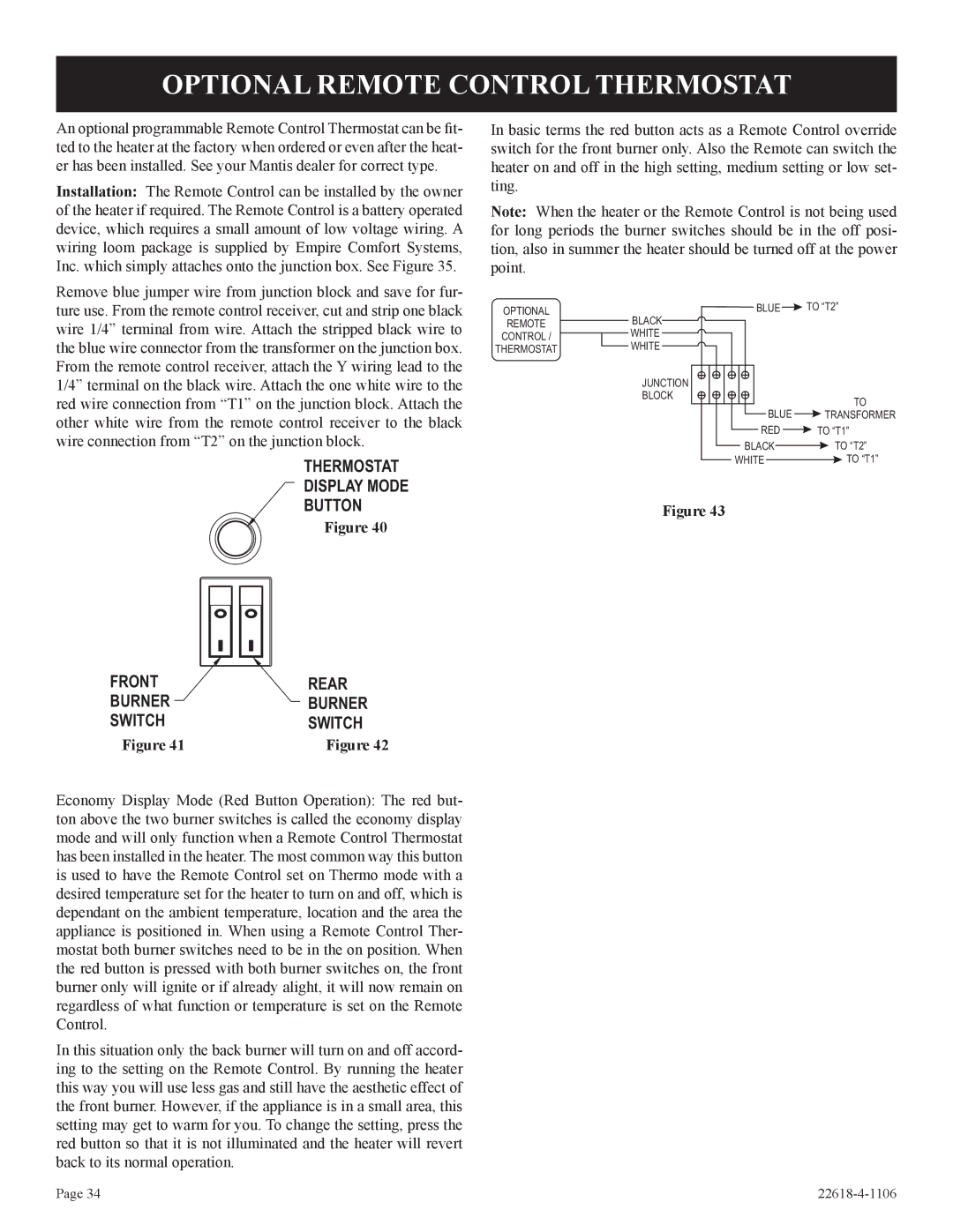
Remove blue jumper wire from junction block and save for fur- ture use. From the remote control receiver, cut and strip one black wire 1/4” terminal from wire. Attach the stripped black wire to the blue wire connector from the transformer on the junction box. From the remote control receiver, attach the Y wiring lead to the 1/4” terminal on the black wire. Attach the one white wire to the red wire connection from “T1” on the junction block. Attach the other white wire from the remote control receiver to the black wire connection from “T2” on the junction block.
THERMOSTAT
DISPLAY MODE
OPTIONAL
REMOTE | BLACK |
| |
CONTROL / | WHITE |
| |
THERMOSTAT | WHITE |
| |
| JUNCTION |
| BLOCK |
BLUE | TO “T2” |
TO
BLUE ![]() TRANSFORMER
TRANSFORMER
RED ![]() TO “T1”
TO “T1”
| BLACK |
| TO “T2” |
|
| ||
WHITE |
| TO “T1” | |
BUTTON
Figure 40
Figure 43
FRONT | REAR |
BURNER | BURNER |
SWITCH | SWITCH |
Figure 41 | Figure 42 |
Economy Display Mode (Red Button Operation): The red but- ton above the two burner switches is called the economy display mode and will only function when a Remote Control Thermostat has been installed in the heater. The most common way this button is used to have the Remote Control set on Thermo mode with a desired temperature set for the heater to turn on and off, which is dependant on the ambient temperature, location and the area the appliance is positioned in. When using a Remote Control Ther- mostat both burner switches need to be in the on position. When the red button is pressed with both burner switches on, the front burner only will ignite or if already alight, it will now remain on regardless of what function or temperature is set on the Remote Control.
In this situation only the back burner will turn on and off accord- ing to the setting on the Remote Control. By running the heater this way you will use less gas and still have the aesthetic effect of the front burner. However, if the appliance is in a small area, this setting may get to warm for you. To change the setting, press the red button so that it is not illuminated and the heater will revert back to its normal operation.
Page 34 |