DIRECT VENT INSTALLATION INSTRUCTIONS
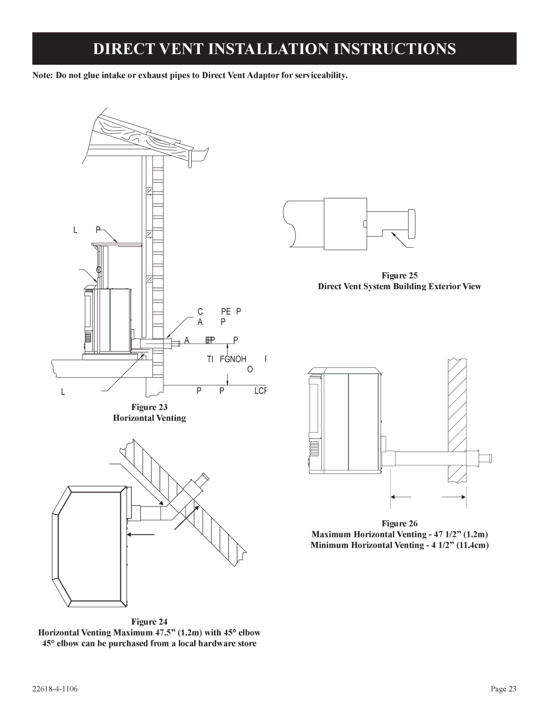
Note: Do not glue intake or exhaust pipes to Direct Vent Adaptor for serviceability.
MANTEL
 EXHAUST OPENING MUST
BE POINTED DOWNWARD.
SURROUND | Figure 25 |
| |
| Direct Vent System Building Exterior View |
DIRECT VENT
FLUE KIT
FLUE CENTER
12” (30.5cm)
MIN.
GAS SUPPLY | EXTERIOR GRADE |
Figure 23
Horizontal Venting
45° ELBOW
| 47.5” | |
| (1.2m) | |
47.5” | Figure 26 | |
Maximum Horizontal Venting - 47 1/2” (1.2m) | ||
(1.2m) | ||
Minimum Horizontal Venting - 4 1/2” (11.4cm) | ||
|
Figure 24
Horizontal Venting Maximum 47.5” (1.2m) with 45° elbow 45° elbow can be purchased from a local hardware store
Page 23 |
