IO-367B specifications
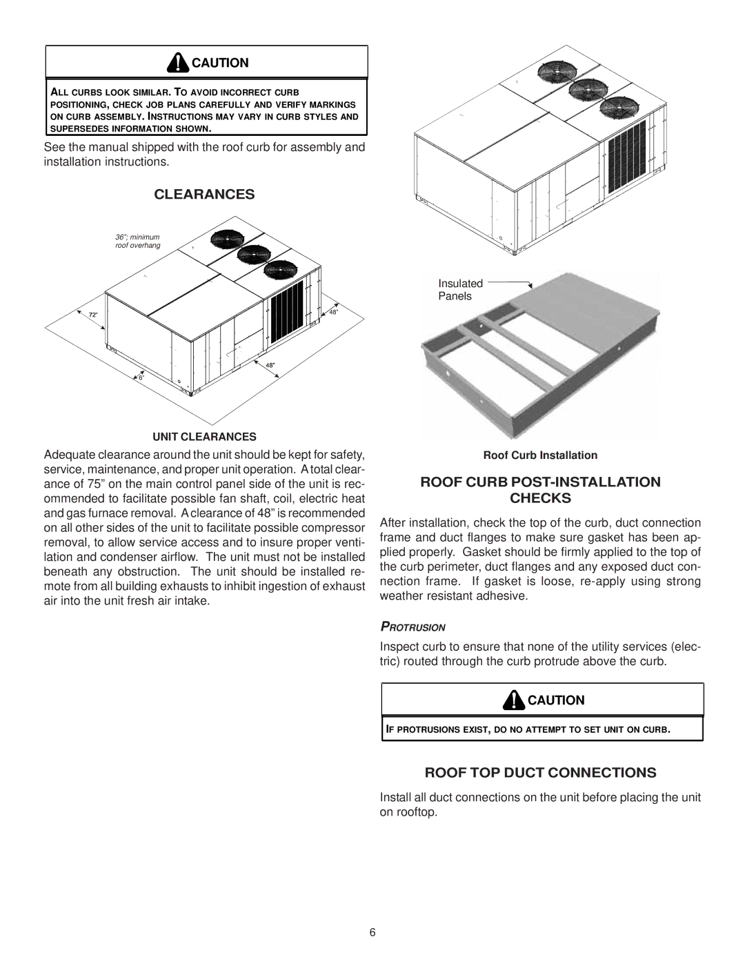
Goodman Manufacturing, a well-respected name in the HVAC industry, offers an impressive range of products tailored to enhance energy efficiency and comfort in residential environments. Among their standout offerings is the IO-367B model, a heat pump designed to deliver exceptional performance, reliability, and user-friendly features.The Goodman IO-367B is a split system heat pump that provides both heating and cooling capabilities, making it a versatile choice for homeowners looking to maintain an optimal indoor climate year-round. Its sleek design allows for easy installation and integration into existing systems, ensuring minimal disruption during the setup process.
One of the key features of the IO-367B is its energy efficiency. With a high SEER (Seasonal Energy Efficiency Ratio) rating, it operates smoothly and effectively while keeping energy consumption low. This not only leads to lower utility bills for homeowners but also supports environmentally friendly practices by reducing the overall carbon footprint. The unit is compliant with the latest energy regulations, making it a future-proof investment for those who prioritize sustainability.
The IO-367B employs advanced technology, including a multi-speed compressor that adjusts operation to meet the specific heating or cooling demands of a space. This feature enhances comfort by reducing temperature fluctuations and maintaining a consistent climate. Additionally, its sound-dampening features ensure quieter operation, making it an excellent choice for both indoor and outdoor installations.
Other notable characteristics include the durable construction of the heat pump, which is designed to withstand varying weather conditions. Its corrosion-resistant cabinet enhances longevity and reliability, ensuring that homeowners can depend on their system for years. Furthermore, Goodman provides a generous warranty on the IO-367B, reflecting their confidence in the product’s durability and performance.
In conclusion, the Goodman IO-367B heat pump stands out in the market due to its energy efficiency, advanced technology, and sturdy design. Ideal for those seeking to enhance their home's comfort while being mindful of energy consumption, this model is a reliable solution for heating and cooling needs.

