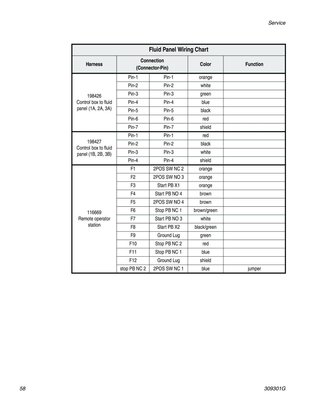
244561 specifications
The Graco 244561 is a highly regarded airless paint sprayer designed for both professional contractors and DIY enthusiasts. It is particularly known for its efficiency and versatility, making it suitable for a wide range of painting projects. This model offers several features that stand out in its class, ensuring that users achieve a high-quality finish with minimal effort.One of the main features of the Graco 244561 is its powerful motor, which delivers consistent pressure for a smooth and even paint application. With a flow rate that can handle up to 0.42 gallons per minute, this sprayer is capable of quickly covering large areas, making it ideal for both interior and exterior projects. The robust design allows for the use of various paint types, including latex and oil-based finishes, giving users flexibility in their material choices.
The Graco 244561 also incorporates advanced technologies aimed at enhancing user experience and improving results. One of these is the Reverse-A-Clean feature, which enables users to easily clear clogs by reversing the flow of paint through the spray tip. This saves time and frustration, allowing users to get back to painting quickly. Additionally, the SmartControl technology ensures a consistent spray pattern at any pressure level, providing control over the finish and ensuring professional quality results.
The sprayer comes with a variety of accessories, including a spray tip that allows for different spray patterns and sizes. This ensures versatility in application, whether you are working on cabinets, walls, fences, or outdoor furniture. The adjustable pressure control also allows users to customize their spray settings based on the project, making it easier to work on intricate details or larger surfaces.
Durability is another key characteristic of the Graco 244561. Built with high-quality materials, this sprayer is designed to withstand the rigors of regular use in various environments. The compact and lightweight design also enhances portability, making it easy to transport from one job site to another.
In conclusion, the Graco 244561 airless paint sprayer is a powerful and versatile tool that caters to a wide array of painting needs. With its efficient motor, innovative technologies, and durable design, it promises excellent performance and reliability for both professionals and DIYers alike. Whether tackling a small home improvement project or a larger commercial job, the Graco 244561 stands out as a reliable choice that combines quality with user-friendliness.

