Manuals
/
Graco
/
Marine Equipment
/
Marine RADAR
Graco
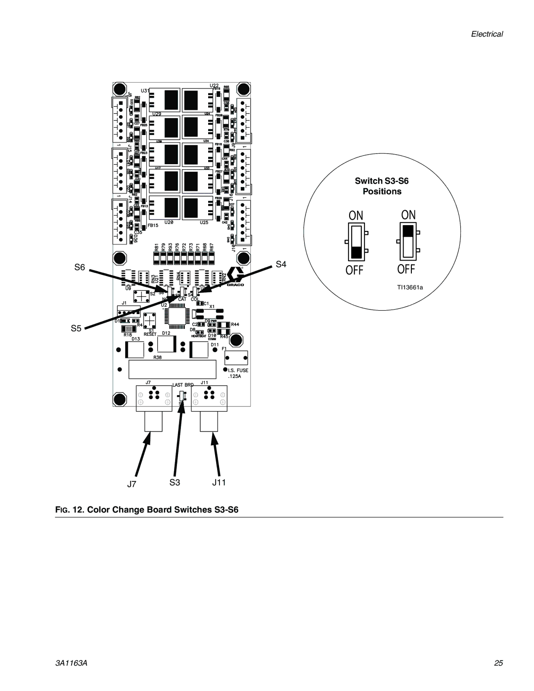
3A1163A Switch S3-S6, Positions, J11 IG . Color Change Board Switches S3-S6
Models:
3A1163A
1
25
36
36
Download
36 pages
53.35 Kb
22
23
24
25
26
27
28
29
Wiring Diagram
Warranty
Accessory
Assembly FC
Technical Data
Switch S3-S6
Page 25
Image 25
Electrical
Switch
S3-S6
Positions
ON
ON
S6
S4
OFF
OFF
TI13661a
S5
J7
S3
J11
F
IG
. 12. Color Change Board Switches
S3-S6
3A1163A
25
Page 24
Page 26
Page 25
Image 25
Page 24
Page 26
Contents
II 2 G
ProControl 1KS
Contents
Equipment Approvals
Related Manuals
Models
System Configuration and Part Numbers
Label Location on EasyKey
Accessory
Feature
Fire and Explosion Hazard
Skin Injection Hazard
Toxic Fluid or Fumes Hazard
Important Two-Component Material Information
Component Identification and Definition
Assembly FC
Control Box Power Supply Cable PS Flow Control
Component Description Fluid Manifold FM
Pneumatically Operated Dose Valve for component a
Location
Intrinsically Safe Installation Requirements
Location Requirements
Optional Cables
Requirements on
NON-HAZARDOUS Hazardous Classified Location Location only
General Information
See Dimensions and Mounting Hole Layouts,
Wall Mounting
ProControl 1KS System Layout Drawing
Wall Mounting
Air Supply
See the System Pneumatic Schematic on
Requirements
Air Connections
Fluid Connections
Fluid Supply
Color Change Valve Stack TI11668a
Color Change Board and Solenoid Valves
Flow Control Regulator
Regulator Fluid Air Fluid Out FC Cable
Electrical
Requirements Connect Main Power
Connect EasyKey to Fluid Station Control
EasyKey Connections and AC Power Switch
Fluid Station Board Connections
Connect Color Change Module
Color Change Board Switch Settings Two Color Change Boards
One Color Change Board
J11 IG . Color Change Board Switches S3-S6
Switch S3-S6
Positions
Wiring Diagram
Check Resistance
Grounding
Robot
EasyKey Display Control Box
System Pneumatic Schematic
Schematic Diagrams
Non-Hazardous Area
System Electrical Schematic
Hazardous Area
Wall Panel Mounting bracket only
Dimensions and Mounting Hole Layouts
Flow Control Module Air Supply Control
EasyKey
Dimensions and Mounting Hole Layouts
Maximum fluid working pressure Maximum working air pressure
Technical Data
Graco Information
Graco Standard Warranty
Top
Page
Image
Contents