Chapter 5 Cabling the RF Switch With the Cisco uBR7246VXR CMTS
Connecting the Cables (Cisco
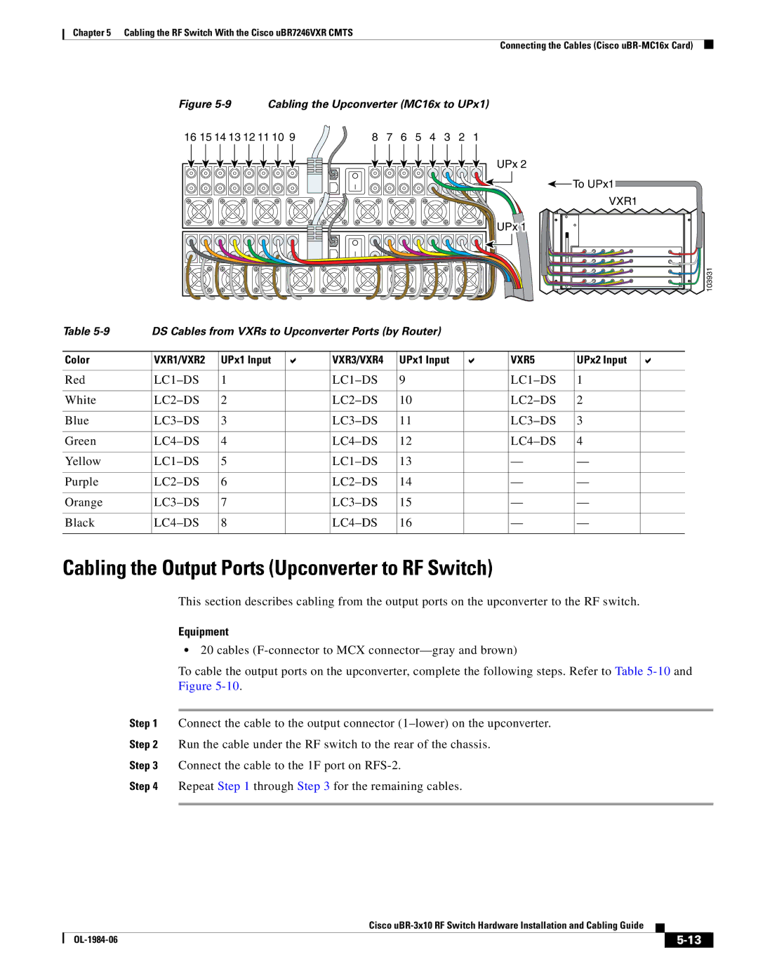
Figure 5-9 Cabling the Upconverter (MC16x to UPx1)
16 15 14 13 12 11 10 9 | 8 | 7 | 6 | 5 | 4 | 3 | 2 | 1 |
UPx 2
UPx 1
![]() To UPx1
To UPx1
VXR1 |
103931 |
Table | DS Cables from VXRs to Upconverter Ports (by Router) |
|
|
|
| ||||
|
|
|
|
|
|
|
|
|
|
Color | VXR1/VXR2 | UPx1 Input |
| VXR3/VXR4 | UPx1 Input |
| VXR5 | UPx2 Input |
|
|
|
|
|
|
|
|
|
|
|
Red | 1 |
| 9 |
| 1 |
| |||
|
|
|
|
|
|
|
|
|
|
White | 2 |
| 10 |
| 2 |
| |||
|
|
|
|
|
|
|
|
|
|
Blue | 3 |
| 11 |
| 3 |
| |||
|
|
|
|
|
|
|
|
|
|
Green | 4 |
| 12 |
| 4 |
| |||
|
|
|
|
|
|
|
|
|
|
Yellow | 5 |
| 13 |
| — | — |
| ||
|
|
|
|
|
|
|
|
|
|
Purple | 6 |
| 14 |
| — | — |
| ||
|
|
|
|
|
|
|
|
|
|
Orange | 7 |
| 15 |
| — | — |
| ||
|
|
|
|
|
|
|
|
|
|
Black | 8 |
| 16 |
| — | — |
| ||
|
|
|
|
|
|
|
|
|
|
Cabling the Output Ports (Upconverter to RF Switch)
This section describes cabling from the output ports on the upconverter to the RF switch.
Equipment
•20 cables
To cable the output ports on the upconverter, complete the following steps. Refer to Table
Step 1 Connect the cable to the output connector
Step 2 Run the cable under the RF switch to the rear of the chassis.
Step 3 Connect the cable to the 1F port on
Step 4 Repeat Step 1 through Step 3 for the remaining cables.
Cisco
|
| ||
|
|