Chapter 6 Troubleshooting
Troubleshooting the Installation and Setup
Cisco uBR 3x10 RF Switch Slot Information
Table
Tip The modules are listed as seen from the front of the RF switch.
8 | Switching Matrix for the Cisco uBR 3x10 RF Switch (Upstream and Downstream Modules) |
| |||||||
Table |
| ||||||||
|
|
|
|
|
|
|
|
|
|
RFS |
|
|
|
| RFS |
|
|
|
|
Module | Working Ports | PROTECT Ports | Type | Module | Working Ports | PROTECT Ports |
| Type | |
|
|
|
|
|
|
|
|
| |
2 | P1H, P2H1 | upstream | 1 | P1A, P2A |
| upstream | |||
4 | P1I, P2I |
| upstream | 3 | P1B, P2B |
| upstream | ||
|
|
|
|
|
|
|
|
|
|
6 | P1J, P2J |
| upstream | 5 | P1C, P2C |
| upstream | ||
|
|
|
|
|
|
|
|
|
|
8 | P1K, P2K |
| upstream | 7 | P1D, P2D |
| upstream | ||
|
|
|
|
|
|
|
|
|
|
10 | P1L, P2L |
| upstream | 9 | P1E, P2E |
| upstream | ||
|
|
|
|
|
|
|
|
| |
12 | P1M, P2M | downstream | 11 | P1F, P2F |
| downstream | |||
|
|
|
|
|
|
|
|
|
|
14 | not used | — |
| — | 13 | P1G, P2G |
| downstream | |
|
|
|
|
|
|
|
|
| |
1. P2 is used only when the switch is in 4 + 1 mode. |
|
|
|
|
|
| |||
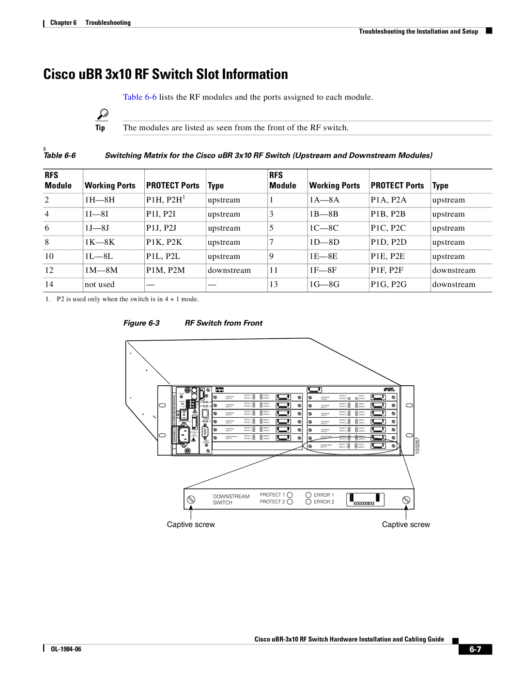
| Figure | RF Switch from Front |
|
|
|
|
| ||
| 103287 |
Captive screw | Captive screw |
Cisco
|
| ||
|
|