Chapter 5 Cabling the RF Switch With the Cisco uBR7246VXR CMTS
Connecting the Cables (Cisco
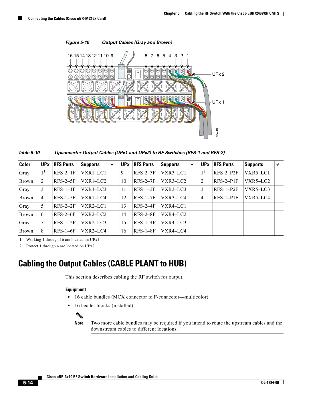
Figure 5-10 Output Cables (Gray and Brown)
16 15 14 13 12 11 10 9 | 8 | 7 | 6 | 5 | 4 | 3 | 2 | 1 |
UPx 2
UPx 1
95743
Table |
| Upconverter Output Cables (UPx1 and UPx2) to RF Switches |
|
| ||||||||
|
|
|
|
|
|
|
|
|
|
|
|
|
Color | UPx | RFS Ports | Supports |
| UPx | RFS Ports | Supports |
| UPx | RFS Ports | Supports |
|
|
|
|
|
|
|
|
|
|
|
|
|
|
Gray | 11 |
| 9 |
| 12 |
| ||||||
Brown | 2 |
| 10 |
|
| 2 |
| |||||
|
|
|
|
|
|
|
|
|
|
|
|
|
Gray | 3 |
| 11 |
| 3 |
| ||||||
|
|
|
|
|
|
|
|
|
|
|
|
|
Brown | 4 |
| 12 |
|
| 4 |
| |||||
|
|
|
|
|
|
|
|
|
|
|
|
|
Gray | 5 |
| 13 |
|
|
|
|
| ||||
|
|
|
|
|
|
|
|
|
|
|
|
|
Brown | 6 |
| 14 |
|
|
|
|
| ||||
|
|
|
|
|
|
|
|
|
|
|
|
|
Gray | 7 |
| 15 |
|
|
|
|
| ||||
|
|
|
|
|
|
|
|
|
|
|
|
|
Brown | 8 |
| 16 |
|
|
|
|
| ||||
|
|
|
|
|
|
|
|
|
|
|
|
|
1.Working 1 through 16 are located on UPx1
2.Protect 1 through 4 are located on UPx2
Cabling the Output Cables (CABLE PLANT to HUB)
This section describes cabling the RF switch for output.
Equipment
•16 cable bundles (MCX connector to
•16 header blocks (installed)
Note Two more cable bundles may be required if you intend to route the upstream cables and the downstream cables to different locations.
Cisco
|
| |
|
