Chapter 3 Installing the Cisco RF Switch
Connecting Power
Step 7 Tighten the receptacle screws and nuts for the +48V and
Step 8 Run the +48V and
Step 9 Adjust the voltage on the DC power supply to approximately
Note Wait until the system has been cabled before turning on the power supply. See the “Powering On the RF Switch” section on page
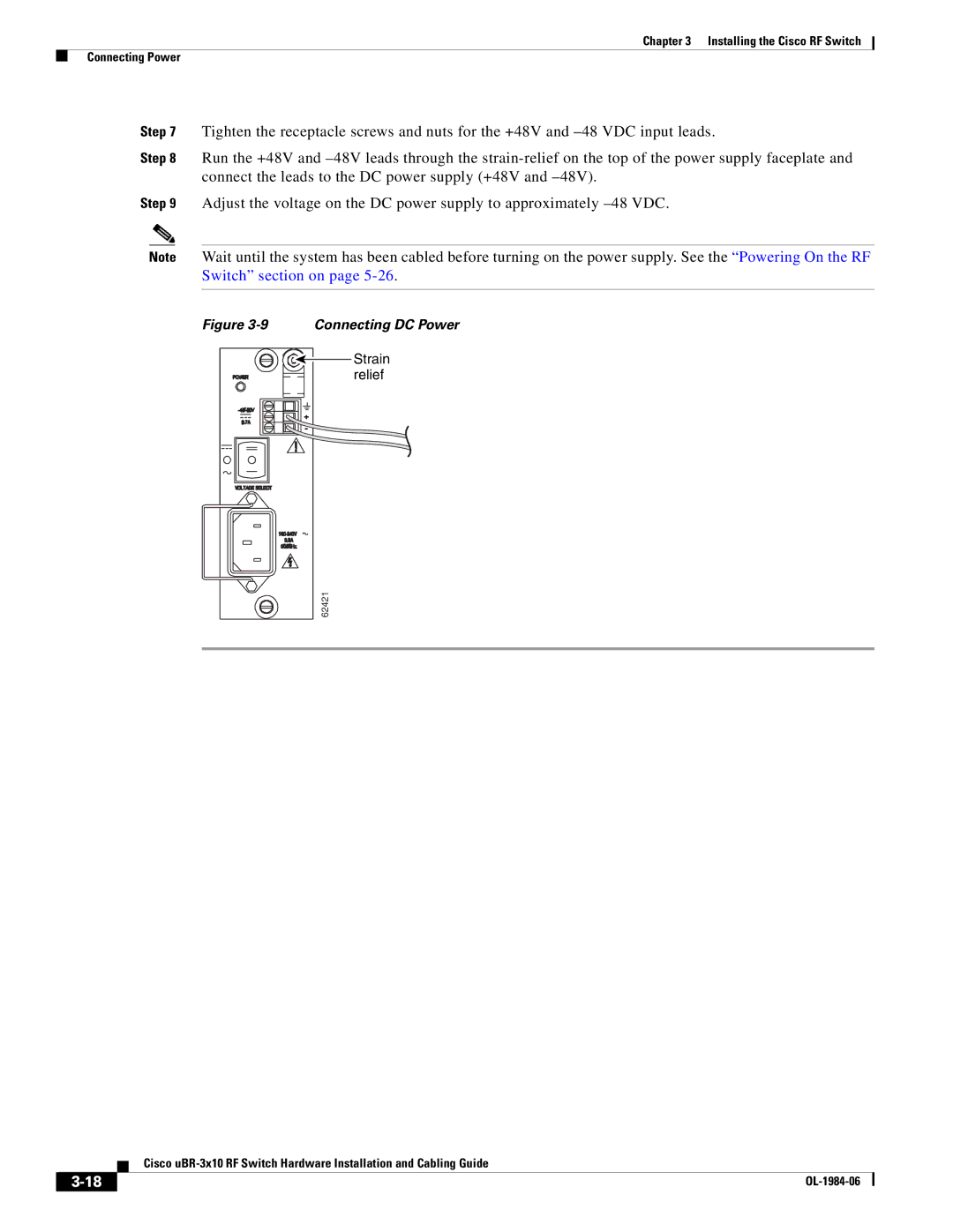
Figure 3-9 Connecting DC Power
Strain relief
62421
Cisco
| ||
|