Chapter 4 Cabling the RF Switch With the Cisco uBR10012 CMTS Cable Interface Line Cards
Connecting the RF Cables (Cisco
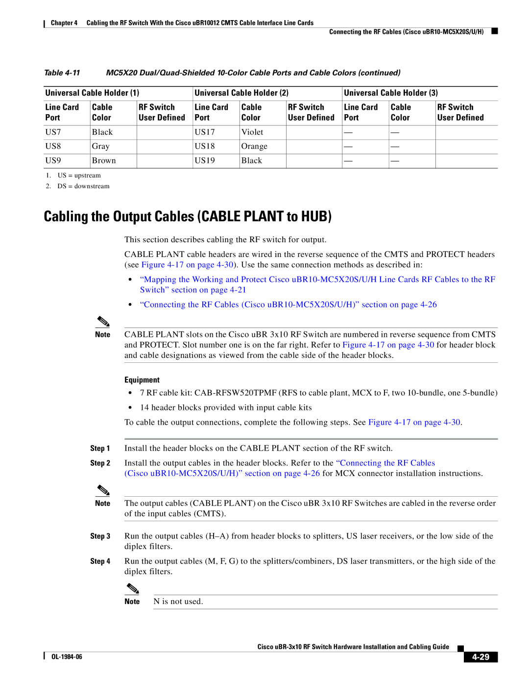
Table | MC5X20 |
| ||||||
|
|
|
|
|
|
| ||
Universal Cable Holder (1) | Universal Cable Holder (2) | Universal Cable Holder (3) | ||||||
|
|
|
|
|
|
|
|
|
Line Card | Cable | RF Switch | Line Card | Cable | RF Switch | Line Card | Cable | RF Switch |
Port | Color | User Defined | Port | Color | User Defined | Port | Color | User Defined |
|
|
|
|
|
|
|
|
|
US7 | Black |
| US17 | Violet |
| — | — |
|
|
|
|
|
|
|
|
|
|
US8 | Gray |
| US18 | Orange |
| — | — |
|
|
|
|
|
|
|
|
|
|
US9 | Brown |
| US19 | Black |
| — | — |
|
|
|
|
|
|
|
|
|
|
1.US = upstream
2.DS = downstream
Cabling the Output Cables (CABLE PLANT to HUB)
This section describes cabling the RF switch for output.
CABLE PLANT cable headers are wired in the reverse sequence of the CMTS and PROTECT headers (see Figure
•“Mapping the Working and Protect Cisco
•“Connecting the RF Cables (Cisco
Note CABLE PLANT slots on the Cisco uBR 3x10 RF Switch are numbered in reverse sequence from CMTS and PROTECT. Slot number one is on the far right. Refer to Figure
Equipment
•7 RF cable kit:
•14 header blocks provided with input cable kits
To cable the output connections, complete the following steps. See Figure
Step 1 Install the header blocks on the CABLE PLANT section of the RF switch.
Step 2 Install the output cables in the header blocks. Refer to the “Connecting the RF Cables
(Cisco
Note The output cables (CABLE PLANT) on the Cisco uBR 3x10 RF Switches are cabled in the reverse order of the input cables (CMTS).
Step 3 Run the output cables
Step 4 Run the output cables (M, F, G) to the splitters/combiners, DS laser transmitters, or the high side of the diplex filters.
Note N is not used.
Cisco
|
| ||
|
|