Chapter 4 Cabling the RF Switch With the Cisco uBR10012 CMTS Cable Interface Line Cards
Connecting the RF Cables (Cisco
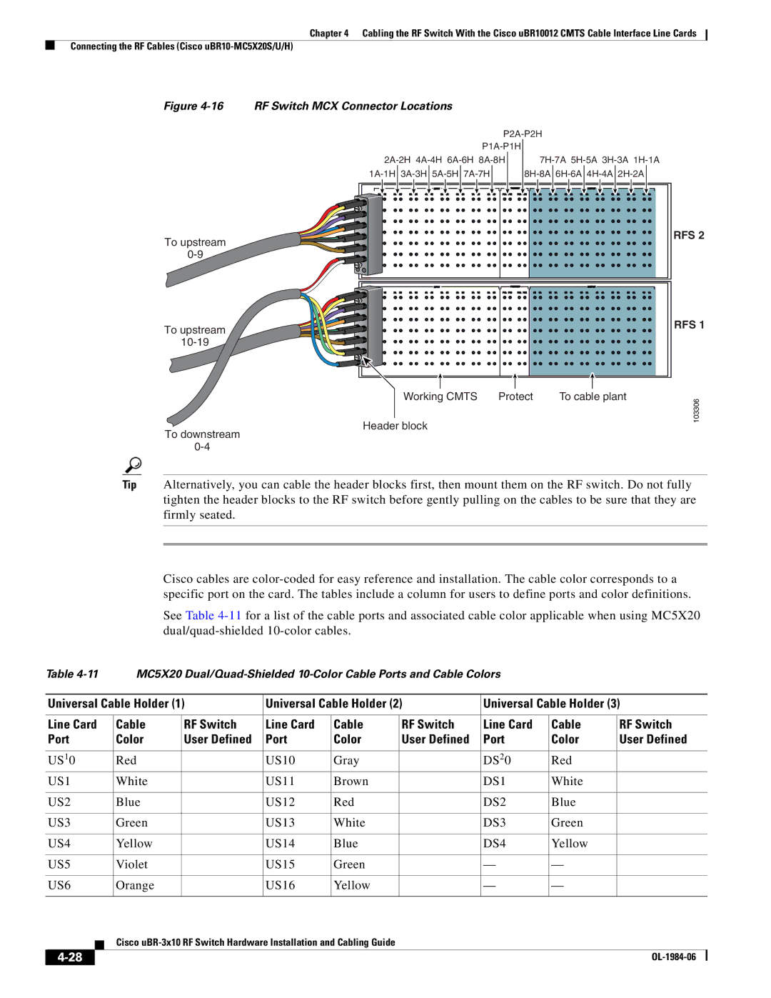
Figure | RF Switch MCX Connector Locations |
|
|
|
|
|
| ||
|
|
| ||
|
| |||
|
| |||
To upstream |
|
|
| RFS 2 |
|
|
|
| |
|
|
|
| |
To upstream |
|
|
| RFS 1 |
|
|
|
| |
|
|
|
| |
| Working CMTS | Protect | To cable plant | 103306 |
| Header block |
|
| |
To downstream |
|
|
| |
|
|
|
| |
|
|
|
| |
Tip Alternatively, you can cable the header blocks first, then mount them on the RF switch. Do not fully tighten the header blocks to the RF switch before gently pulling on the cables to be sure that they are firmly seated.
Cisco cables are
See Table
Table |
| MC5X20 |
|
|
| |||||||
|
|
|
|
|
|
|
| |||||
| Universal Cable Holder (1) | Universal Cable Holder (2) | Universal Cable Holder (3) | |||||||||
|
|
|
|
|
|
|
|
|
|
| ||
| Line Card |
| Cable | RF Switch | Line Card | Cable | RF Switch | Line Card | Cable | RF Switch | ||
| Port |
| Color | User Defined | Port | Color | User Defined | Port | Color | User Defined | ||
|
|
|
|
|
|
|
|
|
|
|
| |
| US10 |
| Red |
| US10 | Gray |
| DS20 | Red |
|
| |
| US1 |
| White |
| US11 | Brown |
| DS1 | White |
|
| |
|
|
|
|
|
|
|
|
|
|
|
| |
| US2 |
| Blue |
| US12 | Red |
| DS2 | Blue |
|
| |
|
|
|
|
|
|
|
|
|
|
|
| |
| US3 |
| Green |
| US13 | White |
| DS3 | Green |
|
| |
|
|
|
|
|
|
|
|
|
|
|
| |
| US4 |
| Yellow |
| US14 | Blue |
| DS4 | Yellow |
|
| |
|
|
|
|
|
|
|
|
|
|
|
| |
| US5 |
| Violet |
| US15 | Green |
| — | — |
|
| |
|
|
|
|
|
|
|
|
|
|
|
| |
| US6 |
| Orange |
| US16 | Yellow |
| — | — |
|
| |
|
|
|
|
|
|
|
|
|
|
|
|
|
|
|
|
| Cisco |
|
|
|
|
| |||
|
|
|
|
|
|
|
| |||||
|
|
|
|
|
|
|
|
|
|
|
|
|
|
|
|
|
|
|
|
|
|
|
| ||
|
|
|
|
|
|
|
|
|
|
| ||