Chapter 4 Cabling the RF Switch With the Cisco uBR10012 CMTS Cable Interface Line Cards
Mapping the RF Cables from the Working and Protect Line Cards (MC16x, MC28C) to the Cisco uBR 3x10 RF Switch
Mapping the RF Cables from the Working and Protect Line Cards (MC16x, MC28C) to the Cisco uBR 3x10 RF Switch
This section provides guidelines for mapping the RF cables and contains the following subsections:
•Mapping the Cisco
•Mapping the Cisco
Note This sample mapping (or any other valid mapping method) is applicable to both working and protect cable interface line cards when employing N+1 redundancy.
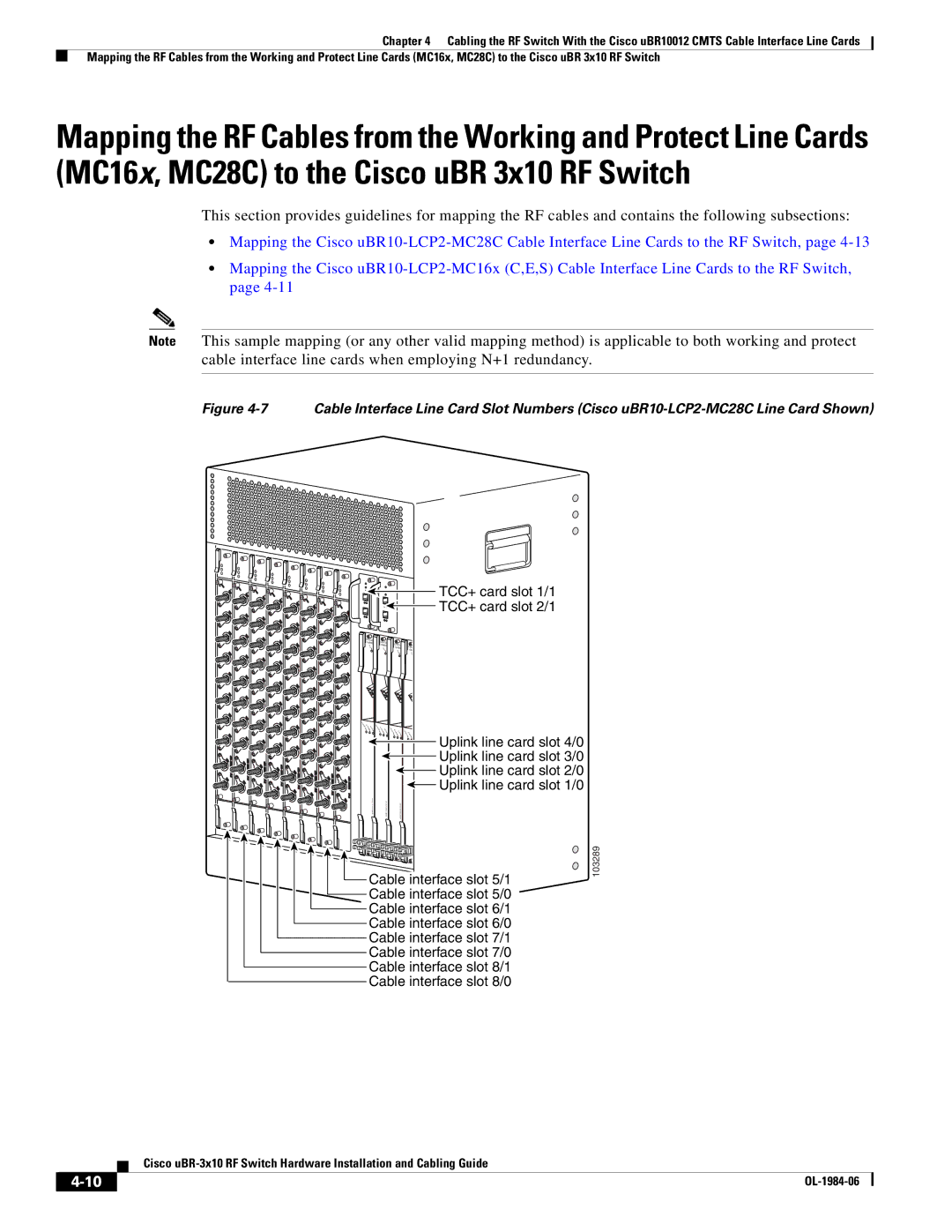
Figure 4-7 Cable Interface Line Card Slot Numbers (Cisco uBR10-LCP2-MC28C Line Card Shown)
E |
|
NAB |
|
LED |
|
U | |
| S0 |
U | |
| S1 |
U | |
| S2 |
U | |
| S3 |
U | |
| S0 |
U | |
| S1 |
U | |
| S2 |
U | |
| S3 |
D | uBR |
S0 | - |
| MC28C |
D |
|
S1 |
|
E |
|
NAB |
|
LED |
|
U | |
| S0 |
U | |
| S1 |
U | |
| S2 |
U | |
| S3 |
U | |
| S0 |
U | |
| S1 |
U | |
| S2 |
U | |
| S3 |
D | uBR |
S0 | - |
| MC28C |
D |
|
S1 |
|
E |
|
NAB |
|
LED |
|
U | |
| S0 |
U | |
| S1 |
U | |
| S2 |
U | |
| S3 |
U | |
| S0 |
U | |
| S1 |
U | |
| S2 |
U | |
| S3 |
D | uBR |
S0 | - |
| MC28C |
D |
|
S1 |
|
E |
|
NAB |
|
LED |
|
U | |
| S0 |
U | |
| S1 |
U | |
| S2 |
U | |
| S3 |
U | |
| S0 |
U | |
| S1 |
U | |
| S2 |
U | |
| S3 |
D | uBR |
S0 | - |
| MC28C |
D |
|
S1 |
|
E |
|
NAB |
|
LED |
|
U | |
| S0 |
U | |
| S1 |
U | |
| S2 |
U | |
| S3 |
U | |
| S0 |
U | |
| S1 |
U | |
| S2 |
U | |
| S3 |
D | uBR |
S0 | - |
| MC28C |
D |
|
S1 |
|
E |
|
NAB |
|
LED |
|
U | |
| S0 |
U | |
| S1 |
U | |
| S2 |
U | |
| S3 |
U | |
| S0 |
U | |
| S1 |
U | |
| S2 |
U | |
| S3 |
D | uBR |
S0 | - |
| MC28C |
D |
|
S1 |
|
E |
|
NAB |
|
LED |
|
U | |
| S0 |
U | |
| S1 |
U | |
| S2 |
U | |
| S3 |
U | |
| S0 |
U | |
| S1 |
U | |
| S2 |
U | |
| S3 |
D | uBR |
S0 | - |
| MC28C |
D |
|
S1 |
|
E |
|
NAB |
|
LED |
|
U | |
| S0 |
U | |
| S1 |
U | |
| S2 |
U | |
| S3 |
U | |
| S0 |
U | |
| S1 |
U | |
| S2 |
U | |
| S3 |
D | uBR |
S0 | - |
| MC28C |
D |
|
S1 |
|
CISCO | CISCO |
|
|
|
10000 | C | ISCO |
| |
FAI | 10000 |
| CISC | |
L | FAI | 10000 | ||
| L |
| FA | 100 |
|
|
| IL | F |
|
|
|
| ALI |
C
A
R
| A |
| CA |
|
|
|
|
|
RI | LA | L |
|
|
|
|
| |
ER RM OOP | RREI ALAR LO | CAR A | CAR A | |||||
|
|
| R | M OP | REI | LAR LO | ||
|
|
|
|
| R | M OP | REIR LARM L | |
|
|
|
|
|
|
|
|
|
|
|
|
|
|
|
|
|
|
|
|
|
|
|
|
|
|
|
|
|
|
|
|
|
|
|
|
TCC+ card slot 1/1 TCC+ card slot 2/1
Uplink line card slot 4/0 Uplink line card slot 3/0 Uplink line card slot 2/0 Uplink line card slot 1/0
![]() Cable interface slot 5/1 Cable interface slot 5/0 Cable interface slot 6/1 Cable interface slot 6/0 Cable interface slot 7/1 Cable interface slot 7/0 Cable interface slot 8/1 Cable interface slot 8/0
Cable interface slot 5/1 Cable interface slot 5/0 Cable interface slot 6/1 Cable interface slot 6/0 Cable interface slot 7/1 Cable interface slot 7/0 Cable interface slot 8/1 Cable interface slot 8/0
103289
Cisco
| ||
|