Chapter 6 Troubleshooting
Troubleshooting the Installation and Setup
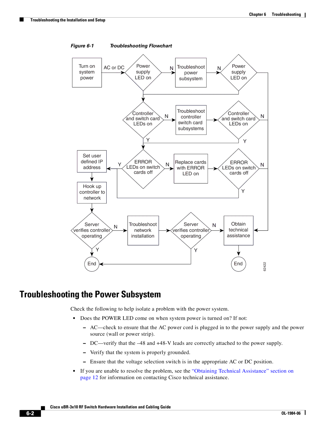
Figure | Troubleshooting Flowchart |
|
|
| |||
Turn on | AC or DC | Power |
| N Troubleshoot | N | Power |
|
system |
| supply |
| power |
| supply |
|
power |
| LED on |
| subsystem |
| LED on |
|
|
| Controller | N | Troubleshoot |
| Controller | N |
|
| controller |
| ||||
|
| and switch card |
| and switch card | |||
|
|
| switch card |
|
| ||
|
| LEDs on |
|
| LEDs on |
| |
|
|
|
| subsystems |
|
|
|
|
| Y |
|
|
| Y |
|
Set user |
|
|
|
|
|
|
|
defined IP | Y | ERROR | N | Replace cards |
| ERROR | N |
address | LEDs on switch | with ERROR |
| LEDs on switch | |||
|
|
|
| ||||
|
| cards off |
| LED on |
| cards off |
|
Hook up |
|
|
|
|
| Y |
|
controller to |
|
|
|
|
| ||
network |
|
|
|
|
|
|
|
Server |
| Troubleshoot |
| Server | N | Obtain |
|
verifies controller N | network |
| verifies controller |
| technical |
| |
operating |
| installation |
| operating |
| assistance |
|
Y |
|
|
| Y |
|
|
|
End |
|
|
|
|
| End | 62422 |
|
|
|
|
|
|
| |
Troubleshooting the Power Subsystem
Check the following to help isolate a problem with the power system.
•Does the POWER LED come on when system power is turned on? If not:
–
–
–Verify that the system is properly grounded.
–Ensure that the voltage selection switch is in the appropriate AC or DC position.
•If you are unable to resolve the problem, see the “Obtaining Technical Assistance” section on page 12 for information on contacting Cisco technical assistance.
Cisco
|
| |
|