Chapter 1 Cisco
Hardware Component Descriptions
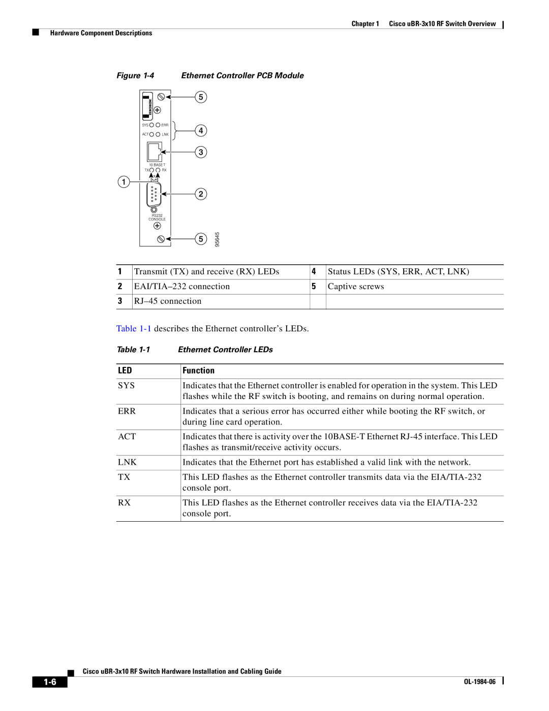
Figure 1-4 Ethernet Controller PCB Module
5 |
|
4 |
|
3 |
|
1 |
|
2 |
|
5 | 95645 |
|
1 | Transmit (TX) and receive (RX) LEDs | 4 | Status LEDs (SYS, ERR, ACT, LNK) |
|
|
|
|
2 | 5 | Captive screws | |
|
|
|
|
3 |
|
| |
|
|
|
|
Table
Table | Ethernet Controller LEDs | |
|
|
|
LED |
| Function |
|
|
|
SYS |
| Indicates that the Ethernet controller is enabled for operation in the system. This LED |
|
| flashes while the RF switch is booting, and remains on during normal operation. |
|
|
|
ERR |
| Indicates that a serious error has occurred either while booting the RF switch, or |
|
| during line card operation. |
|
|
|
ACT |
| Indicates that there is activity over the |
|
| flashes as transmit/receive activity occurs. |
|
|
|
LNK |
| Indicates that the Ethernet port has established a valid link with the network. |
|
|
|
TX |
| This LED flashes as the Ethernet controller transmits data via the |
|
| console port. |
|
|
|
RX |
| This LED flashes as the Ethernet controller receives data via the |
|
| console port. |
|
|
|
Cisco
| ||
|