Chapter 5 Cabling the RF Switch With the Cisco uBR7246VXR CMTS
Connecting the Cables (Cisco
Cabling the Output Ports (Upconverter to RF Switch)
The following section describes cabling from the output ports on the upconverter to the RF switch.
Equipment
•40 cables
To cable the upconverter to the RF switch, complete the following steps. Refer to Figure
Step 1 Connect the cable to the output connector
Step 2 Run the cable under the RF switch to the rear of the chassis.
Step 3 Connect the cable to the F1 port on the header block.
a.See Table
b.See Table
c.See Table
Step 4 Repeat Step 1 through Step 3 for the remaining cables, alternating between the F and M ports on the header blocks.
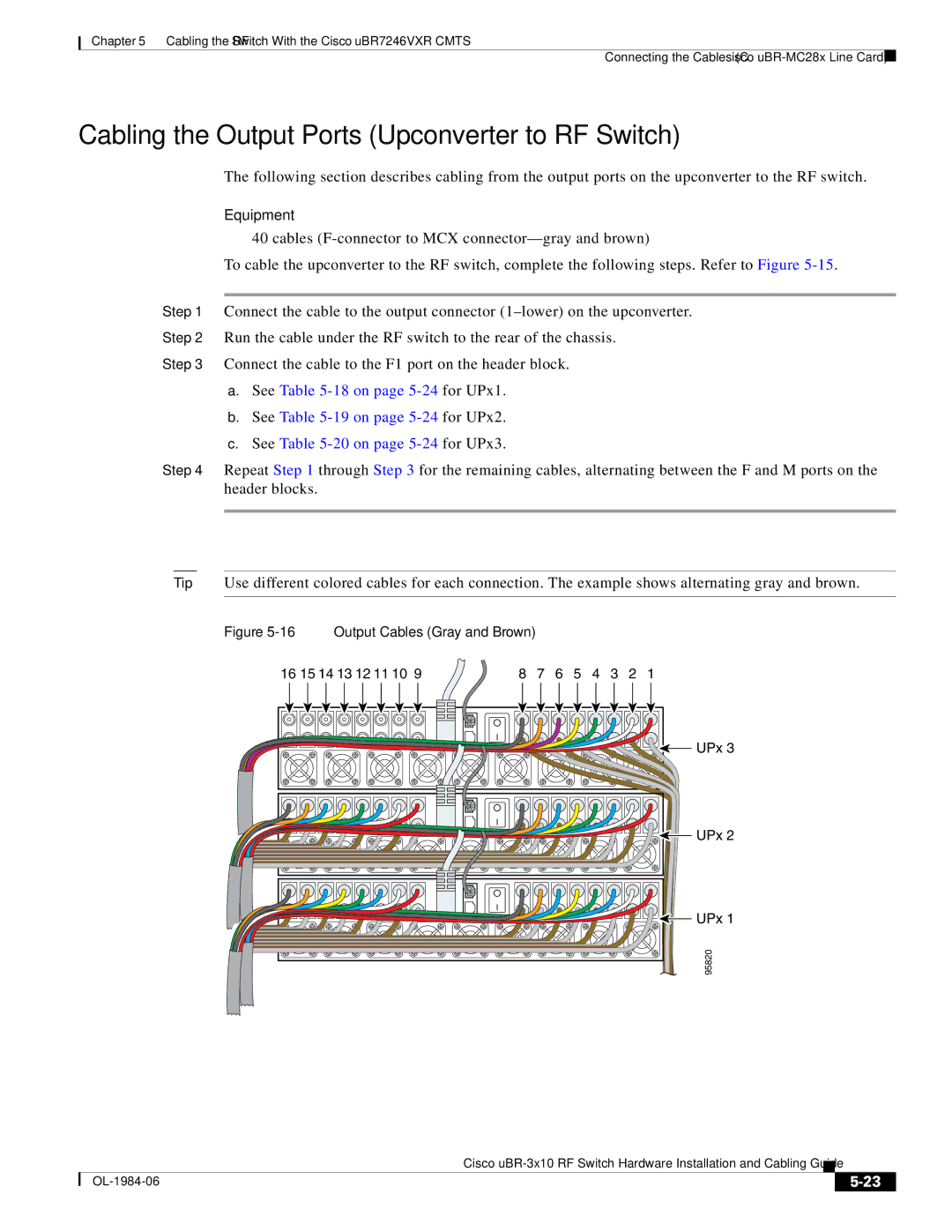
Tip Use different colored cables for each connection. The example shows alternating gray and brown.
Figure 5-16 Output Cables (Gray and Brown)
16 15 14 13 12 11 10 9 | 8 | 7 | 6 | 5 | 4 | 3 | 2 | 1 |
UPx 3 |
UPx 2 |
UPx 1 |
95820 |
Cisco
|
| ||
|
|