Chapter 5 Cabling the RF Switch With the Cisco uBR7246VXR CMTS
Connecting the Cables (Cisco
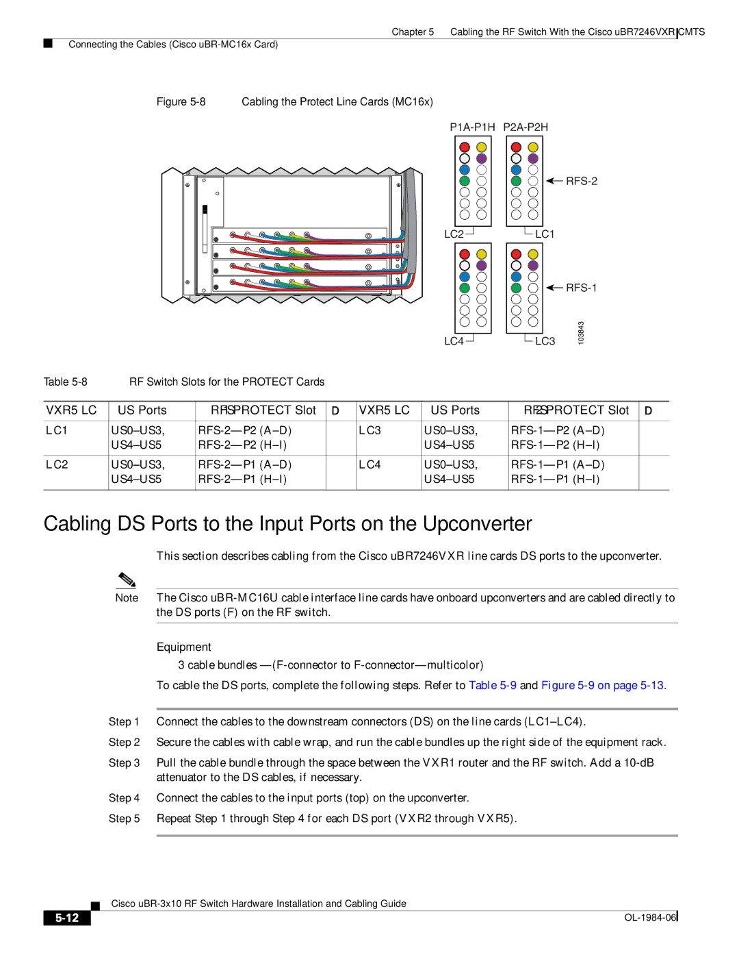
Figure 5-8 Cabling the Protect Line Cards (MC16x)
![]()
|
|
|
|
|
|
|
|
|
LC2 |
|
|
|
|
| LC1 | ||
|
| |||||||
![]()
|
|
|
|
|
|
|
|
|
LC4 |
|
|
|
|
| LC3 | ||
|
| |||||||
103843
Table | RF Switch Slots for the PROTECT Cards |
|
|
|
| ||
|
|
|
|
|
|
|
|
| US Ports |
| US Ports |
| |||
|
|
|
|
|
|
|
|
LC1 |
| LC3 |
| ||||
|
|
|
| ||||
|
|
|
|
|
|
|
|
LC2 |
| LC4 |
| ||||
|
|
|
| ||||
|
|
|
|
|
|
|
|
Cabling DS Ports to the Input Ports on the Upconverter
This section describes cabling from the Cisco uBR7246VXR line cards DS ports to the upconverter.
Note The Cisco
Equipment
•3 cable bundles
To cable the DS ports, complete the following steps. Refer to Table
Step 1 Connect the cables to the downstream connectors (DS) on the line cards
Step 2 Secure the cables with cable wrap, and run the cable bundles up the right side of the equipment rack.
Step 3 Pull the cable bundle through the space between the VXR1 router and the RF switch. Add a
Step 4 Connect the cables to the input ports (top) on the upconverter.
Step 5 Repeat Step 1 through Step 4 for each DS port (VXR2 through VXR5).
Cisco
|
| |
|