Chapter 4 Cabling the RF Switch With the Cisco uBR10012 CMTS Cable Interface Line Cards
Connecting the RF Cables (MC16x, MC28C Line Cards)
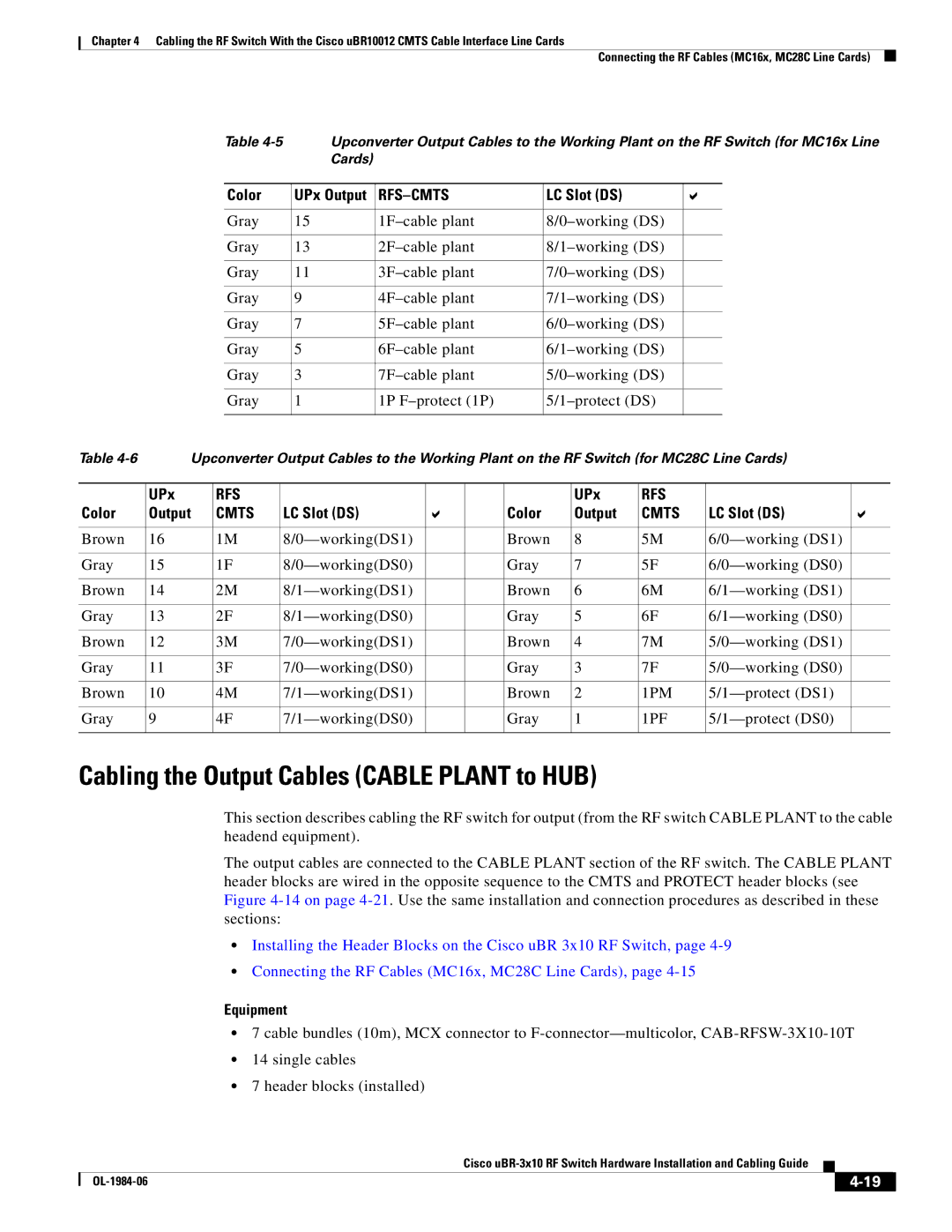
Table | Upconverter Output Cables to the Working Plant on the RF Switch (for MC16x Line | ||||
| Cards) |
|
|
|
|
|
|
|
|
|
|
Color | UPx Output |
| LC Slot (DS) |
|
|
|
|
|
|
|
|
Gray | 15 |
|
| ||
|
|
|
|
|
|
Gray | 13 |
|
| ||
|
|
|
|
|
|
Gray | 11 |
|
| ||
|
|
|
|
|
|
Gray | 9 |
|
| ||
|
|
|
|
|
|
Gray | 7 |
|
| ||
|
|
|
|
|
|
Gray | 5 |
|
| ||
|
|
|
|
|
|
Gray | 3 |
|
| ||
|
|
|
|
|
|
Gray | 1 | 1P |
|
| |
|
|
|
|
|
|
Table | Upconverter Output Cables to the Working Plant on the RF Switch (for MC28C Line Cards) | |||||||||
|
|
|
|
|
|
|
|
|
|
|
| UPx | RFS |
|
|
|
| UPx | RFS |
|
|
Color | Output | CMTS | LC Slot (DS) |
|
| Color | Output | CMTS | LC Slot (DS) |
|
|
|
|
|
|
|
|
|
|
|
|
Brown | 16 | 1M |
|
| Brown | 8 | 5M |
| ||
|
|
|
|
|
|
|
|
|
|
|
Gray | 15 | 1F |
|
| Gray | 7 | 5F |
| ||
|
|
|
|
|
|
|
|
|
|
|
Brown | 14 | 2M |
|
| Brown | 6 | 6M |
| ||
|
|
|
|
|
|
|
|
|
|
|
Gray | 13 | 2F |
|
| Gray | 5 | 6F |
| ||
|
|
|
|
|
|
|
|
|
|
|
Brown | 12 | 3M |
|
| Brown | 4 | 7M |
| ||
|
|
|
|
|
|
|
|
|
|
|
Gray | 11 | 3F |
|
| Gray | 3 | 7F |
| ||
|
|
|
|
|
|
|
|
|
|
|
Brown | 10 | 4M |
|
| Brown | 2 | 1PM |
| ||
|
|
|
|
|
|
|
|
|
|
|
Gray | 9 | 4F |
|
| Gray | 1 | 1PF |
| ||
|
|
|
|
|
|
|
|
|
|
|
Cabling the Output Cables (CABLE PLANT to HUB)
This section describes cabling the RF switch for output (from the RF switch CABLE PLANT to the cable headend equipment).
The output cables are connected to the CABLE PLANT section of the RF switch. The CABLE PLANT header blocks are wired in the opposite sequence to the CMTS and PROTECT header blocks (see Figure
•Installing the Header Blocks on the Cisco uBR 3x10 RF Switch, page
•Connecting the RF Cables (MC16x, MC28C Line Cards), page
Equipment
•7 cable bundles (10m), MCX connector to
•14 single cables
•7 header blocks (installed)
Cisco
|
| ||
|
|