Chapter 1 Cisco
Hardware Component Descriptions
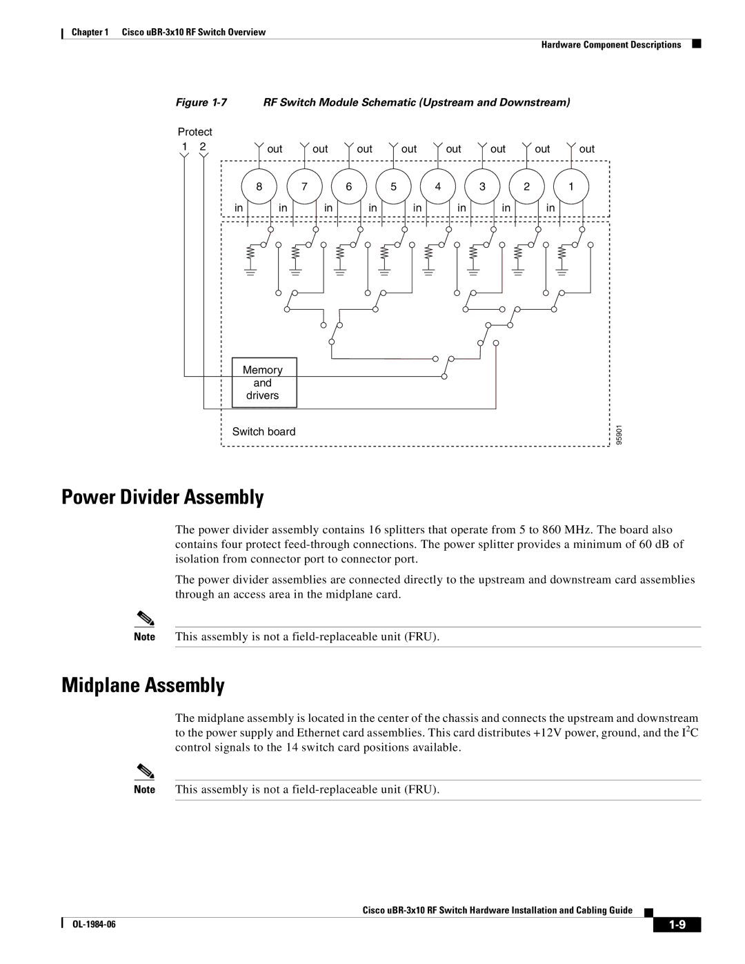
Figure 1-7 RF Switch Module Schematic (Upstream and Downstream)
Protect |
|
|
|
|
|
|
|
| |
1 | 2 | out | out | out | out | out | out | out | out |
|
| 8 | 7 | 6 | 5 | 4 | 3 | 2 | 1 |
| in | in | in | in | in | in | in | in |
|
| Memory |
|
|
|
|
|
|
| |
|
| and |
|
|
|
|
|
|
|
|
| drivers |
|
|
|
|
|
|
|
Switch board | 95901 |
|
Power Divider Assembly
The power divider assembly contains 16 splitters that operate from 5 to 860 MHz. The board also contains four protect
The power divider assemblies are connected directly to the upstream and downstream card assemblies through an access area in the midplane card.
Note This assembly is not a
Midplane Assembly
The midplane assembly is located in the center of the chassis and connects the upstream and downstream to the power supply and Ethernet card assemblies. This card distributes +12V power, ground, and the I2C control signals to the 14 switch card positions available.
Note This assembly is not a
Cisco
|
| ||
|
|