Chapter 4 Cabling the RF Switch With the Cisco uBR10012 CMTS Cable Interface Line Cards
Mapping the Working and Protect Cisco
Mapping the Working and Protect Cisco
This section describes the mapping of RF cables from the working and protect line cards to the Cisco uBR 3x10 RF Switch. Refer to Figure
When you connect RF cables between the RF switch and a cable interface line card installed in a Cisco uBR10012 chassis, ensure that all the RF cables in the bundle attach to interfaces on the same cable interface line card installed in the Cisco uBR10012 chassis. (Refer to Table
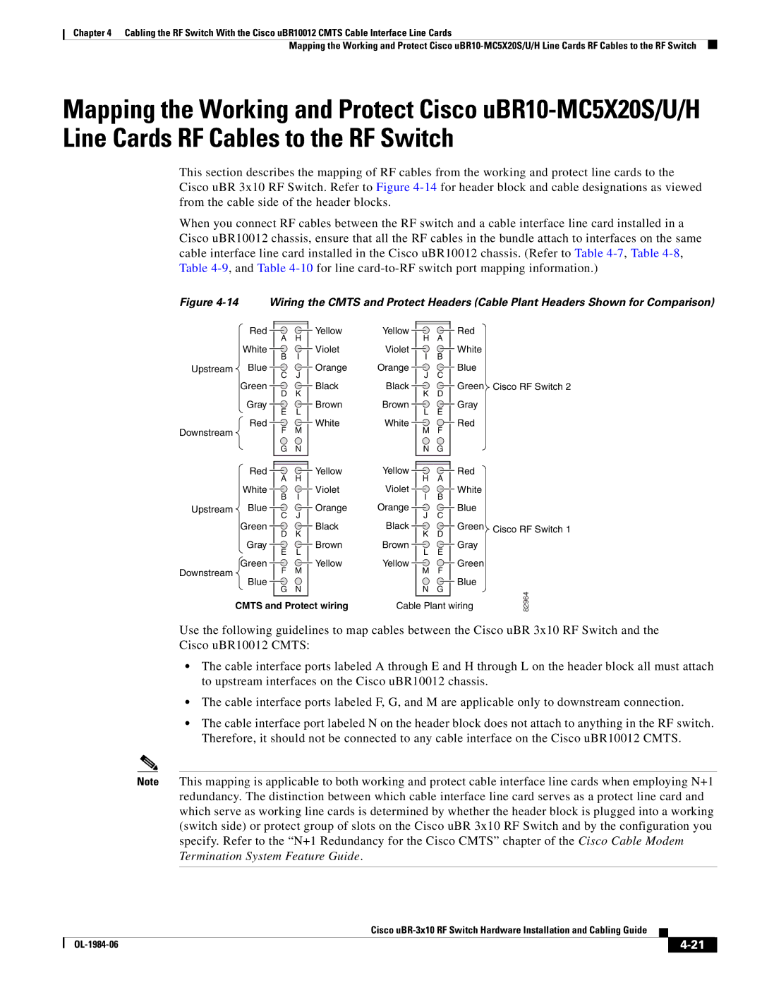
Figure 4-14 Wiring the CMTS and Protect Headers (Cable Plant Headers Shown for Comparison)
Red
White
Upstream Blue
Green
Gray
Red
Downstream
AH
BI
CJ
DK
EL
FM
GN
Yellow Yellow
VioletViolet
Orange Orange
BlackBlack
Brown Brown
WhiteWhite
HA I B J C K D L E M F N G
Red
White
Blue
Green Cisco RF Switch 2 Gray
Red
Red
White
Upstream Blue
Green
Gray
Green
Downstream
Blue
A H
B | I |
C | J |
D | K |
E | L |
F | M |
G | N |
Yellow
Violet
Orange
Black
Brown
Yellow
Yellow | Red |
|
H | A |
|
Violet | White |
|
I | B |
|
Orange | Blue |
|
J | C |
|
Black | Green | Cisco RF Switch 1 |
K | D |
|
Brown | Gray |
|
L | E |
|
Yellow | Green |
|
M | F |
|
| Blue |
|
N G |
82964 |
CMTS and Protect wiring
Cable Plant wiring |
Use the following guidelines to map cables between the Cisco uBR 3x10 RF Switch and the
Cisco uBR10012 CMTS:
•The cable interface ports labeled A through E and H through L on the header block all must attach to upstream interfaces on the Cisco uBR10012 chassis.
•The cable interface ports labeled F, G, and M are applicable only to downstream connection.
•The cable interface port labeled N on the header block does not attach to anything in the RF switch. Therefore, it should not be connected to any cable interface on the Cisco uBR10012 CMTS.
Note This mapping is applicable to both working and protect cable interface line cards when employing N+1 redundancy. The distinction between which cable interface line card serves as a protect line card and which serve as working line cards is determined by whether the header block is plugged into a working (switch side) or protect group of slots on the Cisco uBR 3x10 RF Switch and by the configuration you specify. Refer to the “N+1 Redundancy for the Cisco CMTS” chapter of the Cisco Cable Modem Termination System Feature Guide.
Cisco
|
| ||
|
|