Chapter 3 Installing the Cisco RF Switch
Installation Checklist
Checklist
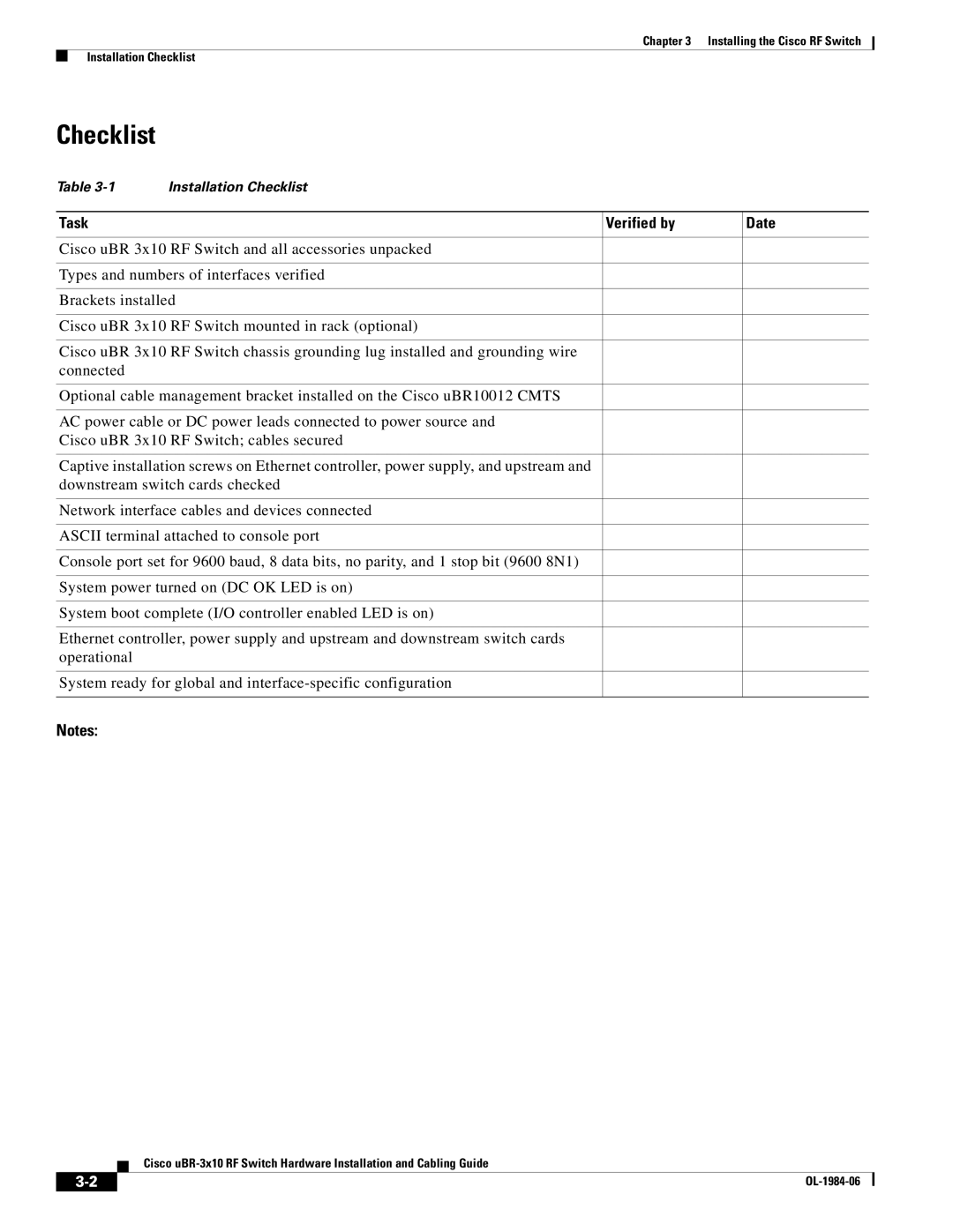
Table | Installation Checklist |
| |
|
|
|
|
Task |
| Verified by | Date |
|
|
| |
Cisco uBR 3x10 RF Switch and all accessories unpacked |
|
| |
|
|
| |
Types and numbers of interfaces verified |
|
| |
|
|
| |
Brackets installed |
|
| |
|
|
| |
Cisco uBR 3x10 RF Switch mounted in rack (optional) |
|
| |
|
|
| |
Cisco uBR 3x10 RF Switch chassis grounding lug installed and grounding wire |
|
| |
connected |
|
|
|
|
|
| |
Optional cable management bracket installed on the Cisco uBR10012 CMTS |
|
| |
|
|
| |
AC power cable or DC power leads connected to power source and |
|
| |
Cisco uBR 3x10 RF Switch; cables secured |
|
| |
|
|
| |
Captive installation screws on Ethernet controller, power supply, and upstream and |
|
| |
downstream switch cards checked |
|
| |
|
|
| |
Network interface cables and devices connected |
|
| |
|
|
| |
ASCII terminal attached to console port |
|
| |
|
|
| |
Console port set for 9600 baud, 8 data bits, no parity, and 1 stop bit (9600 8N1) |
|
| |
|
|
| |
System power turned on (DC OK LED is on) |
|
| |
|
|
| |
System boot complete (I/O controller enabled LED is on) |
|
| |
|
|
| |
Ethernet controller, power supply and upstream and downstream switch cards |
|
| |
operational |
|
|
|
|
|
| |
System ready for global and |
|
| |
|
|
|
|
Notes:
Cisco
| ||
|