Appendix A Specifications and Component Part Numbers
RF Specifications
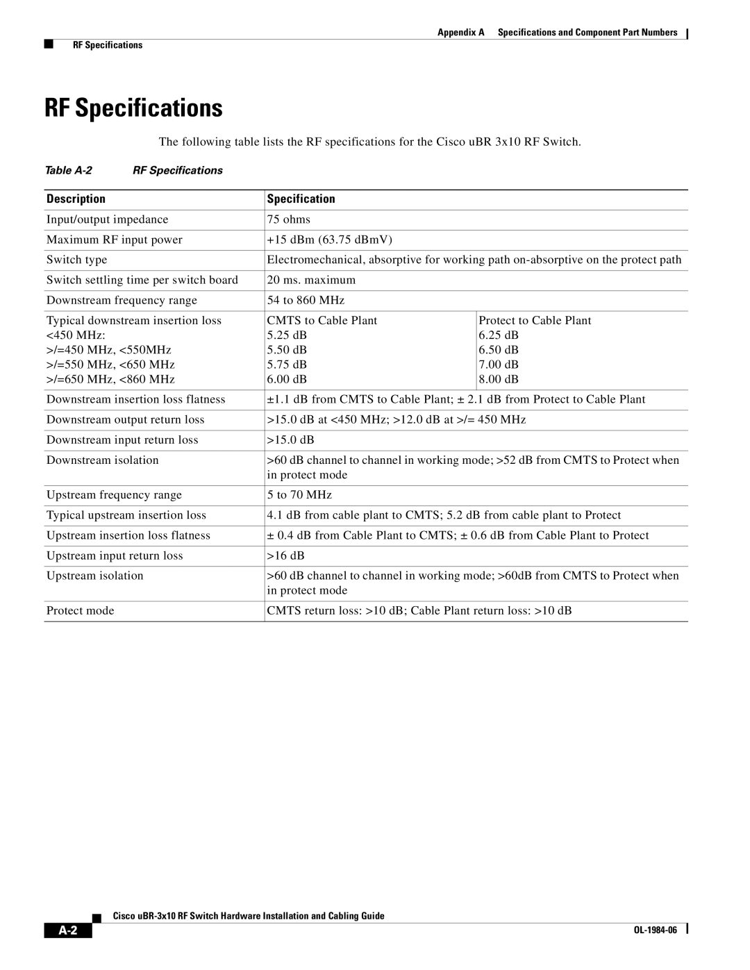
RF Specifications
The following table lists the RF specifications for the Cisco uBR 3x10 RF Switch.
Table | RF Specifications |
|
|
|
|
|
|
Description |
| Specification |
|
|
|
| |
Input/output impedance | 75 ohms |
| |
|
|
| |
Maximum RF input power | +15 dBm (63.75 dBmV) |
| |
|
|
| |
Switch type |
| Electromechanical, absorptive for working path | |
|
|
| |
Switch settling time per switch board | 20 ms. maximum |
| |
|
|
| |
Downstream frequency range | 54 to 860 MHz |
| |
|
|
| |
Typical downstream insertion loss | CMTS to Cable Plant | Protect to Cable Plant | |
<450 MHz: |
| 5.25 dB | 6.25 dB |
>/=450 MHz, <550MHz | 5.50 dB | 6.50 dB | |
>/=550 MHz, <650 MHz | 5.75 dB | 7.00 dB | |
>/=650 MHz, <860 MHz | 6.00 dB | 8.00 dB | |
|
|
| |
Downstream insertion loss flatness | ±1.1 dB from CMTS to Cable Plant; ± 2.1 dB from Protect to Cable Plant | ||
|
| ||
Downstream output return loss | >15.0 dB at <450 MHz; >12.0 dB at >/= 450 MHz | ||
|
|
| |
Downstream input return loss | >15.0 dB |
| |
|
| ||
Downstream isolation | >60 dB channel to channel in working mode; >52 dB from CMTS to Protect when | ||
|
| in protect mode |
|
|
|
| |
Upstream frequency range | 5 to 70 MHz |
| |
|
| ||
Typical upstream insertion loss | 4.1 dB from cable plant to CMTS; 5.2 dB from cable plant to Protect | ||
|
| ||
Upstream insertion loss flatness | ± 0.4 dB from Cable Plant to CMTS; ± 0.6 dB from Cable Plant to Protect | ||
|
|
| |
Upstream input return loss | >16 dB |
| |
|
| ||
Upstream isolation | >60 dB channel to channel in working mode; >60dB from CMTS to Protect when | ||
|
| in protect mode |
|
|
|
| |
Protect mode |
| CMTS return loss: >10 dB; Cable Plant return loss: >10 dB | |
|
|
|
|
Cisco
|
|
| |
|
|