Chapter 3 Installing the Cisco RF Switch
Connecting Power
Tools and Equipment
•Grounding lug
•Two M5 (metric)
•
•Grounding wire (4 AWG
•One segment of 1.5 in. (3.8 cm) length of 0.5 in. (1.2 cm) diameter heatshrink tubing.
•Heating device for the heatshrink tubing.
Note The
To connect the grounding wire to the Cisco uBR 3x10 RF Switch:
Step 1 Ensure that the Cisco uBR 3x10 RF Switch is powered off and that you have disconnected the AC power cord or DC power leads from the power supply.
Step 2 Strip approximately 0.75 in. (2 cm) of shielding from one end of the grounding wire.
Step 3 Insert the stripped end of the grounding wire into the open end of the grounding lug and crimp the grounding lug securely to the grounding wire.
Step 4 Slide the segment of heatshrink tubing over the joint of the grounding lug and grounding wire so that the exposed connection is covered.
Step 5 Shrink the tubing in place using a suitable heating device.
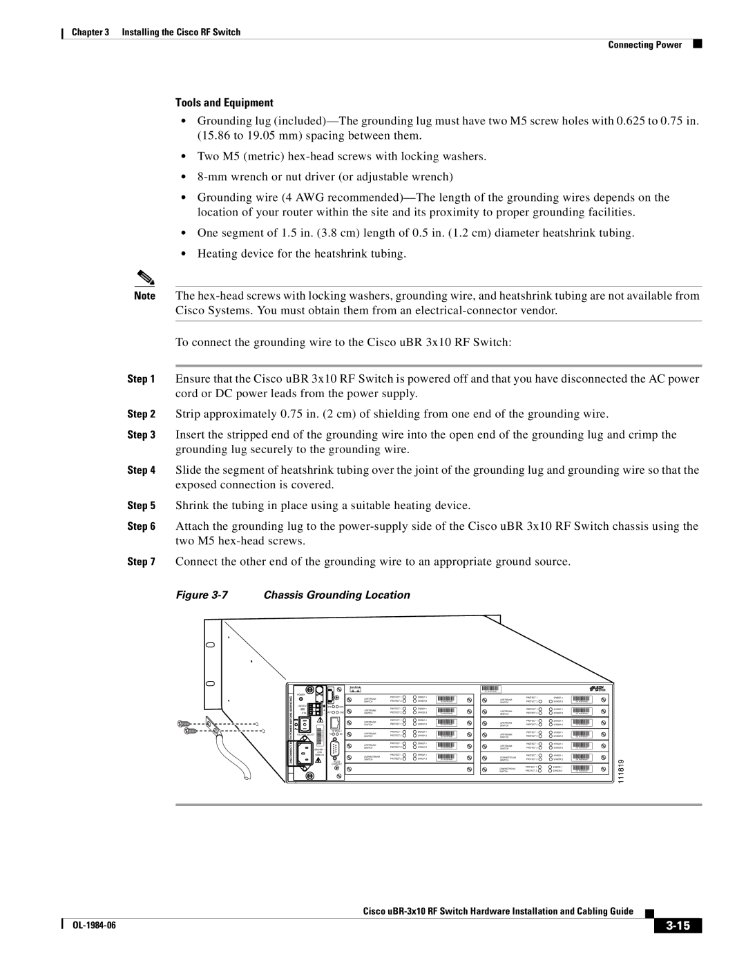
Step 6 Attach the grounding lug to the
Step 7 Connect the other end of the grounding wire to an appropriate ground source.
Figure 3-7 Chassis Grounding Location
|
| SN: NNNNNNNN |
|
| SN: NNNNNNNN | SN: NNNNNNNN |
|
| SN: NNNNNNNN | SN: NNNNNNNN |
|
| SN: NNNNNNNN | SN: NNNNNNNN |
|
NNNNNNNNSN: | SN: NNNNNNNN | SN: NNNNNNNN |
|
| SN: NNNNNNNN | SN: NNNNNNNN |
|
| SN: NNNNNNNN | SN: NNNNNNNN | 111819 |
|
| SN: NNNNNNNN |
Cisco
|
| ||
|
|