Cisco Systems UBR-3X10 manual 4-20, To cable the output connections, complete the following steps

Models: UBR-3X10

1 128
Download 128 pages 7 Kb
Page 74
Image 74
To cable the output connections, complete the following steps.

Chapter 4 Cabling the RF Switch With the Cisco uBR10012 CMTS Cable Interface Line Cards

Connecting the RF Cables (MC16x, MC28C Line Cards)

Tip For shorter cables (3m) use cable kit CAB-RFSW520TPMF (dual-shielded) or CAB-RFSW520QTPMF (quad-shielded).

To cable the output connections, complete the following steps.

Step 1 Install the header blocks on the CABLE PLANT section of the RF switch. Refer to Installing the Header Blocks on the Cisco uBR 3x10 RF Switch, page 4-9, if necessary.

Step 2 Install the output cables in the header blocks. Refer to Mapping the Cisco uBR10-LCP2-MC28C Cable Interface Line Cards to the RF Switch, page 4-13for RF switch/MCX connector installation instructions, if necessary.

Step 3 Run the output cables (H–A) from header blocks to splitters, US laser receivers, or the low side of the diplex filters

Step 4 Run the output cables (F) or (M–F) to the splitters/combiners, DS laser transmitters, or the high side of the diplex filters.

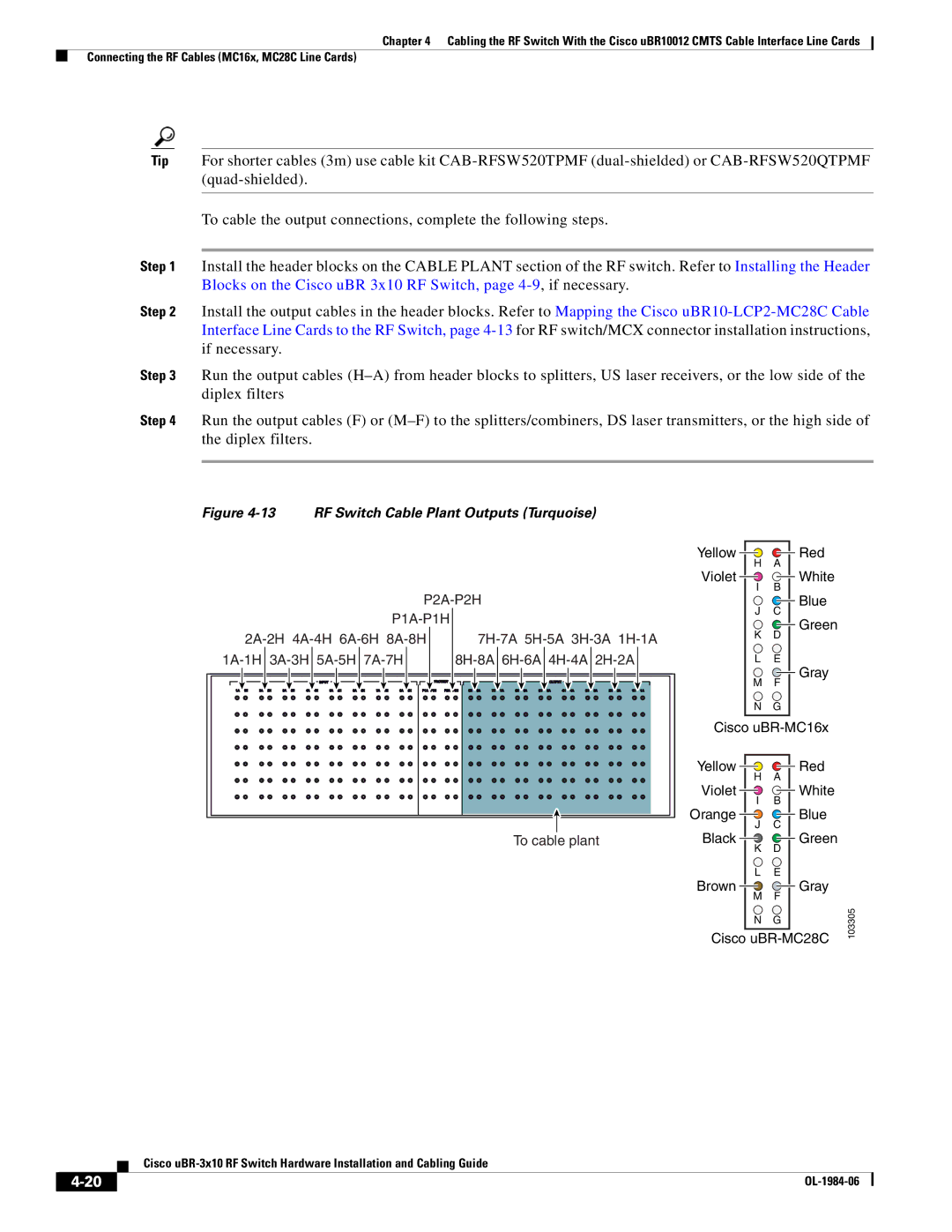
Figure 4-13 RF Switch Cable Plant Outputs (Turquoise)

P2A-P2H

P1A-P1H


2A-2H 4A-4H 6A-6H 8A-8H

7H-7A 5H-5A 3H-3A 1H-1A

1A-1H 3A-3H 5A-5H 7A-7H

8H-8A 6H-6A 4H-4A 2H-2A

To cable plant

Yellow

Red

H

A

Violet

White

I

B

J

Blue

C

K

Green

D

L

E


Gray

MF

NG

Cisco uBR-MC16x

Yellow

Red

H

A

Violet

White

I

B

Orange

Blue

J

C

Black

Green

KD

LE

Brown 4-20Manual background Gray

M

F

103305

N

G


Cisco uBR-MC28C

Cisco uBR-3x10 RF Switch Hardware Installation and Cabling Guide

4-20

OL-1984-06


Page 74
Image 74
Cisco Systems UBR-3X10 manual 4-20, To cable the output connections, complete the following steps