Chapter 1 Cisco
Hardware Component Descriptions
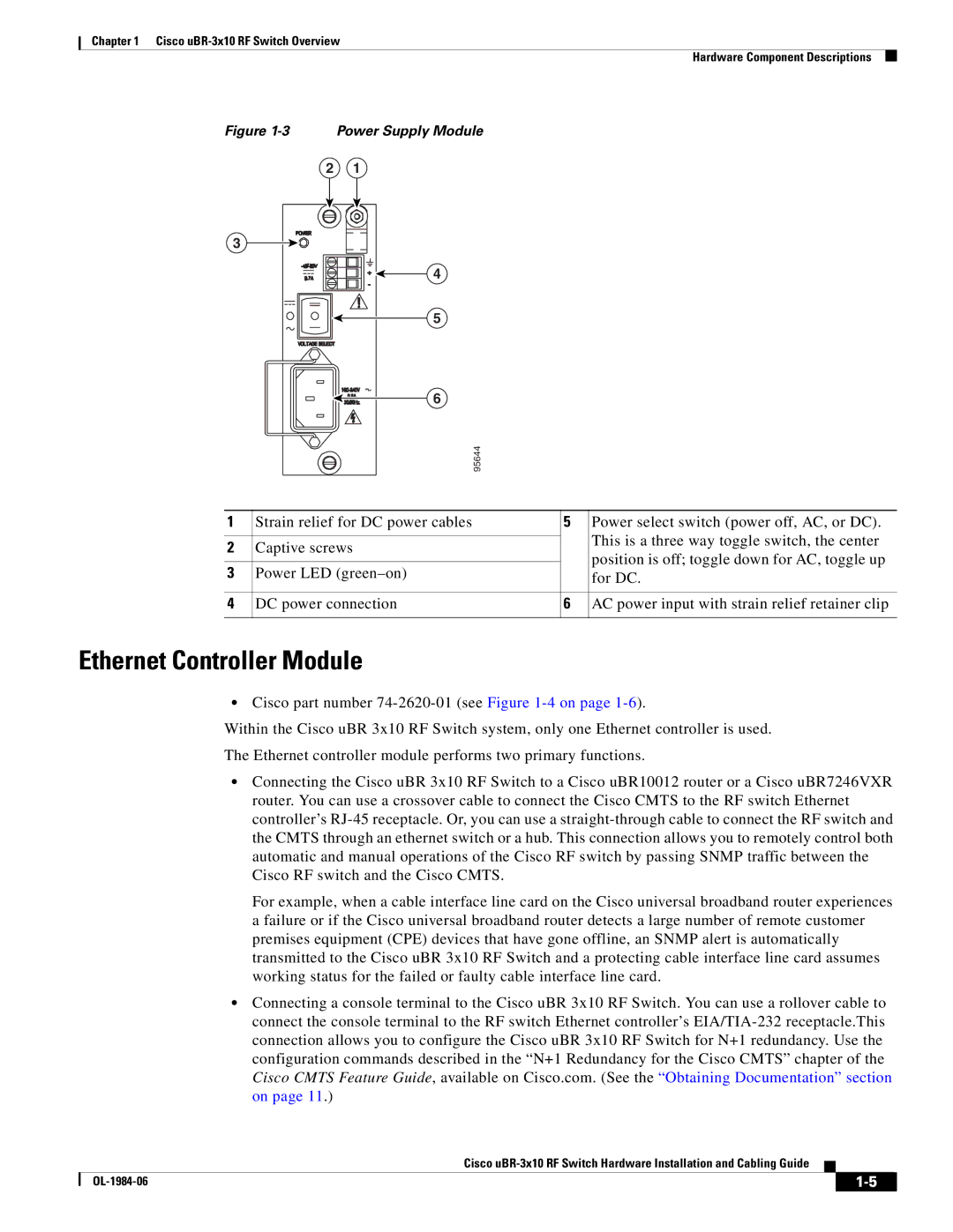
Figure 1-3 Power Supply Module
2 | 1 |
3 |
|
| 4 |
| 5 |
| 6 |
| 95644 |
1 | Strain relief for DC power cables | 5 | Power select switch (power off, AC, or DC). |
|
|
| This is a three way toggle switch, the center |
2 | Captive screws |
| |
| position is off; toggle down for AC, toggle up | ||
|
|
| |
3 | Power LED |
| |
| for DC. | ||
|
|
|
|
4 | DC power connection | 6 | AC power input with strain relief retainer clip |
|
|
|
|
Ethernet Controller Module
•Cisco part number
Within the Cisco uBR 3x10 RF Switch system, only one Ethernet controller is used.
The Ethernet controller module performs two primary functions.
•Connecting the Cisco uBR 3x10 RF Switch to a Cisco uBR10012 router or a Cisco uBR7246VXR router. You can use a crossover cable to connect the Cisco CMTS to the RF switch Ethernet controller’s
For example, when a cable interface line card on the Cisco universal broadband router experiences a failure or if the Cisco universal broadband router detects a large number of remote customer premises equipment (CPE) devices that have gone offline, an SNMP alert is automatically transmitted to the Cisco uBR 3x10 RF Switch and a protecting cable interface line card assumes working status for the failed or faulty cable interface line card.
•Connecting a console terminal to the Cisco uBR 3x10 RF Switch. You can use a rollover cable to connect the console terminal to the RF switch Ethernet controller’s
Cisco
|
| ||
|
|