Chapter 1 Cisco
Hardware Component Descriptions
Downstream Switch Module
•Cisco part number
Three downstream
Note See Chapter 4, “Cabling the RF Switch With the Cisco uBR10012 CMTS Cable Interface Line Cards,” for more cabling information.
The downstream switch module accepts signal inputs (eight) from the power combiner and combines one of the eight to a protect output. Alternately, the switch splits the inputs into two groups of four and then selects one input (in the group of four) to combine with the protect input. The relays are electromechanical, latching relays that are controlled through an I2C interface. The switch card provides a minimum of 60 dB of isolation from connector port to connector port.
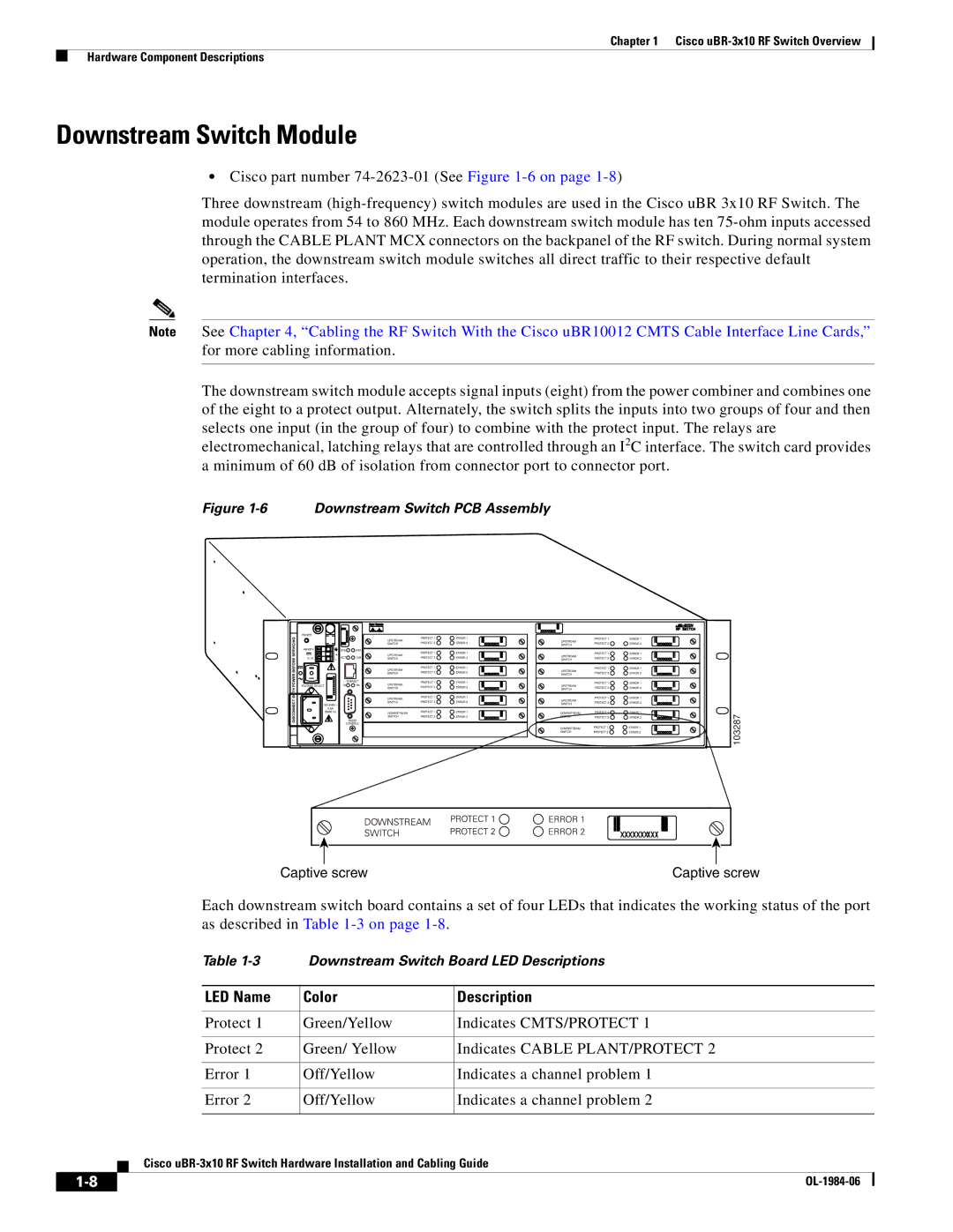
Figure 1-6 Downstream Switch PCB Assembly
103287 |
|
|
|
|
| Captive screw | Captive screw | ||
|
|
|
| Each downstream switch board contains a set of four LEDs that indicates the working status of the port | ||||
|
|
|
| as described in Table |
|
| ||
|
|
|
| Table |
| Downstream Switch Board LED Descriptions | ||
|
|
|
|
|
|
|
| |
|
|
|
| LED Name |
| Color | Description | |
|
|
|
|
|
|
|
| |
|
|
|
| Protect 1 |
| Green/Yellow | Indicates CMTS/PROTECT 1 | |
|
|
|
|
|
|
|
| |
|
|
|
| Protect 2 |
| Green/ Yellow | Indicates CABLE PLANT/PROTECT 2 | |
|
|
|
|
|
|
|
| |
|
|
|
| Error 1 |
| Off/Yellow | Indicates a channel problem 1 | |
|
|
|
|
|
|
|
| |
|
|
|
| Error 2 |
| Off/Yellow | Indicates a channel problem 2 | |
|
|
|
|
|
|
| ||
|
|
| Cisco | |||||
|
|
| ||||||
|
|
|
|
|
|
|
|
|
|
|
|
|
|
|
| ||
|
|
|
|
|
|
| ||