User’s Guide
For immediate technical or application assistance
Trademarks
Foreword
Revisions
Electronic Manuals Provided on the Accompanying CD-ROM
RD100B Versions and Functions
Recorder’s Version and Functions Described in This Manual
Software Sold Separately
Version Suffix Code Added or Modified Functions Reference
Safety Standards and EMC Standards
Safety Precautions
About This Manual
Iii
Exemption from Responsibility
Handling Precautions of the Software
Checking the Contents of the Package
Checking the Contents of the Package
Standard Accessories
Optional Accessories Sold Separately
Pen Model
Removing the Packing Materials
Dot Model
Vii
Viii
How to Use This Manual
Conventions Used in This Manual
Contents
Contents
Setup Operations for Convenient Functions Setting Mode
Xii
Maintenance
Overview of the Recorder
Input Section
Measuring Input Section
Square Root Computation
Measuring Input Section Delta Computation
Scaling
Measuring Input Section Bias
Burnout Detection of Thermocouples
Reference Junction Compensation of Thermocouple Input
Measuring Input Section
Noise Elimination from Input Signals
Filter and Moving Average
Filter Pen Model
Model Integration Time of the A/D Converter
Integration Time of the A/D Converter
Alarm Types
Alarms
Delay Low Limit Alarm t
Alarms Delay High Limit Alarm T
Delay High Limit Alarm Example T is the specified delay
Alarm Hysteresis
Alarm Recording
Alarm Indication
Alarm Output Relay /A1, /A2, and /A3 Options
Non-Hold/Hold Operation of the Alarm Indication
Channel Approx ms Approx ms
Alarms Reflash Alarm
Alarm
Energized/De-energized Operation of Alarm Output Relays
Alarms AND/OR Operation of Alarm Output Relays
Functional
Description
Alarms Non-Hold/Hold Operation of Alarm Output Relays
Alarm ACK Operation
Recording
Trend Recording
Chart Speed
Recording Method Pen Model
Recording Method Dot Model
Pen Offset Compensation Pen Model
Recording Partial Expanded Recording
Compressed Expanded
Same time
Printout Example on the Pen Model
Printout
Functional Description Channel Printout Dot Model Only
Recording Printout Example on the Dot Model
Printout Contents for details, see appendix
Recording Alarm Printout
Periodic Printout
Interval
Recording Turning ON/OFF the Periodic Printout
New Chart Speed Printout
Manual Printout
Message Printout
Printout Example of List on the Pen Model
Recording Setting Printout
Printout Example of List on the Dot Model
Display Types
Display
Displayed Information
Date/Time and Chart Speed
Alarm Status Display
Channel Digital + 1 Bar Graph Display
Flag Display
Computation Function
Computation Function /M1 Option
Channels Dedicated to Computations
Types of Computations
Recording Computation Channels
Handing of the Unit in Computations
Trend Recording
Assignment of Computation Channels to the Pens Pen Model
Display
Alarms
Starting/Stopping Computation
Printout
Chart End Output
FAIL/Chart End Detection and Output Function /F1 Option
Fail Output
Fail Relay Output
Remote Control Function /R1 Option
Computation Reset
Remote Control Function /R1 Option Computation Start/Stop
Remote Signal Edge, Trigger, and Level
Rising/Falling edge Trigger Level Ms or more
Other Functions
Temperature Unit
Key Lock
Language
Before Using the Recorder
Handling Precautions
Handling Precautions
Installation Location
Installation
Installation
Installation Procedure
Front Contact With each other
Flat blade
Panel Cutout
External Dimensions of the Recorder
Precautions to Be Taken While Wiring
Input Signal Wiring
General Precautions to Be Taken While Wiring
Measuring input terminal block
Arrangement of the Measuring Input Terminals
Screw input terminal
Clamped input terminal H2 option
Recorder
Input Signal Wiring Dot Model
Before Using
DC current input +/A Shunt resistor
Measuring Input Wiring
Input Signal Wiring
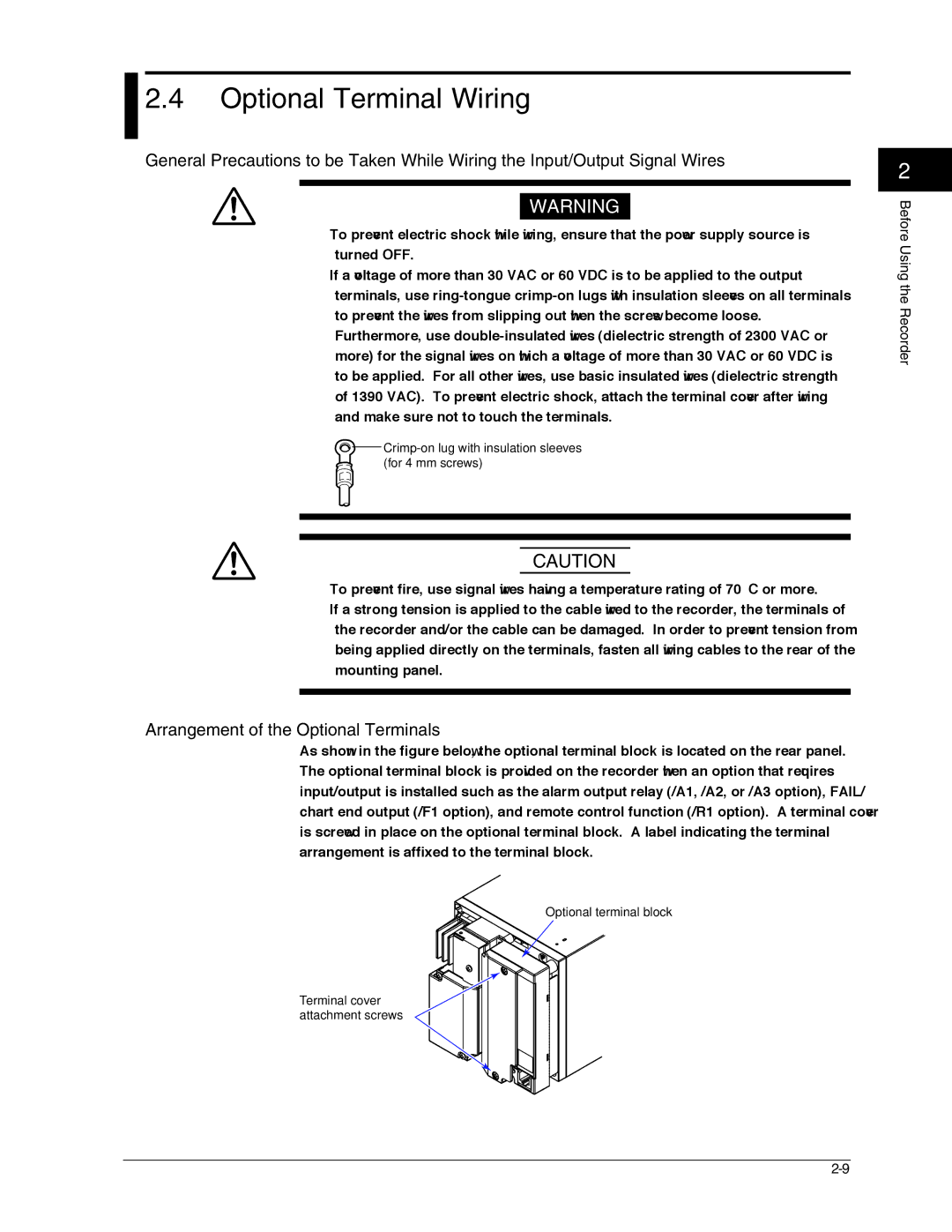
Arrangement of the Optional Terminals
Optional Terminal Wiring
Crimp-on lug with insulation sleeves for 4 mm screws
Optional terminal block
Remote Control Input Terminals
Optional Terminal Wiring
Relay Contact Output Specifications
Wiring Procedure
Relay Contact Input/Transistor Input Specifications
Relay contact output Voltage-free contact Open collector
Power Supply Specifications
Power Supply Wiring
Precautions to Be Taken While Wiring the Power Supply
Power Supply Wiring
Checking the Date/Time
Turning ON/OFF the Power Switch
Front
Names of Parts
Names of Parts and Run Operations
Names of Parts
Status display
Display and Key Panel
Seven keys are available
During normal operation CH UP key
Names Parts Run Operations
Rear Panel
Stopper
Installing or Replacing the Chart Paper
Loading the Chart Paper
Fold chart paper Sprocket teeth
Installing or Replacing the Chart Paper
Chart holder
Side with
Feeding the Chart Paper
Display and key panel
Installing/Replacing Felt Pens or Plotter Pen Pen Model
Replacing Felt Pens
Replacing the Plotter Pen
Holder tab
Installing/Replacing the Ribbon Cassette Dot Model
Hole for the ribbon Feed shaft Ribbon feeding knob
Installing/Replacing the Ribbon Cassette Dot Model
Cassette holder
Starting/Stopping the Recording
Recorded chart paper can be pulled out Front cover tab
Starting the Recording
Stopping the Recording
Switching the Display Screen
Switching the Display Screen
Channel Auto Switching
Switching the Displayed Channel Using Keys
Aborting the Manual Printout
Printing Measured Values Manual Printout
Starting the Manual Printout
Starting the Setup Printout
Printing the Recorder Settings
Aborting the Setup Printout
Starting the List Printout
Buf.clear=Alarm
Clearing the Alarm Printout Buffer
Printing Messages
Displays the preset message
Printing a Message
Clearing the Message Printout Buffer
Resetting the Report Data
Resetting the Report Data of the Periodic Printout
Releasing the Alarm Output
Releasing the Alarm Output Alarm ACK Operation
Alarm Output Relay Operation
Alarm Alarm output relay Blinking Alarm indication
Releasing the Key Lock
Activating/Releasing the Key Lock
Activating the Key Lock
Run Modes
Entering Basic Setting Mode
Entering Setting Mode
Exiting from Setting Mode Returning to Operation Mode
Exiting from Basic Setting Mode Returning to Operation Mode
Using the ESC Key
Changing the Settings
Entering Values
Key Operations
Inserting Characters
Entering Characters
Deleting a Character
Copying & Pasting a Character String
Operation Menus Using the Func Key Operation Mode
Menu Structure, Settings, and List of Default Values
Exchange Dot Model
Menu Structure, Settings, and List of Default Values
Menu Structure of Setting Mode
POC
Menu Structure of Basic Setting Mode
Setup Items in Setting Mode and Their Default Values
RJC RJC
Setup Items in Basic Setting Mode and Their Default Values
Remote control function /R1 option
Setting initialization
NORMAL/MODBUS Normal
Description Reference Section
Function Setup Guide
Recording functions Description Reference Section
Function Setup Guide
Alarm functions Description Reference Section
Recording color
Channel number
Or tag
Other functions Description Reference Section
Display functions Description Reference Section
Computed value
Timer number
TC, RTD, and DC Voltage
Setting the Input Range
Frequently Used Setup Operations Setting Mode
Selectable Range of Input Range, Span Left, and Span Right
Setting the Input range
N1 Option
Input Type
Linear Scaling
First channel Last channel
Delta Computation
Span Left and Span Right
Range Type Selectable Span Values
ON/OFF Input
Scale Left and Scale Right
5V Input
Low-cut
Select the right scale value
To 5.0% of the recording span, 0.1 steps
Square Root Computation
Low-cut and Low-cut Point
Skip Unused Channels
Set the channel range Select Skip New setting takes effect
Setting the Alarm
Alarm Type
Setting the Alarm
Symbol Name
Channel Range
Relay No
Difference High Limit Alarm/Difference Low Limit Alarm
Setting the Unit on Scaled Channels
Mode
Changing the Chart Speed
Chart speed on the pen model unit mm/h
Recorders with Version 1.02 or Earlier
Setting the Date/Time
Date/Time New setting takes effect
Setup Operations for Convenient Functions Setting Mode
Setting the Trend Recording Interval Dot Model
Functions Setting Mode
When set to Auto
Filter Time Constant
Setting the Filter Pen Model
Number of Samples of Moving Average
Setting the Moving Average Dot Model
New setting takes effect
Zone
Setting Recording Zones for Each Channel Zone Recording
Expand
Setting the Partial Expanded Recording
Trend Recording Dot Model
Characters That Can Be Used for Tags
Setting Tags on Channels
Characters That Can Be Used for Messages
Setting the Message String
See section
Duration New setting takes effect
Setting the Alarm Delay Duration
Internal Light Brightness
Setting the Brightness of the Display and Internal Light
Display Brightness
When bias is On
Applying a Bias on the Measuring Input Signal
Setup Operations For Convenient Functions Setting Mode
End month, End day, and End time
Start month, Strt day, and Start time
DST
Changing the Settings
Changing the Auxiliary Alarm Function
Diagnosis
Changing the Auxiliary Alarm Function
Indicator
Changing the Auxiliary Alarm Function Reflash
Act
Behavior
Integrate
Changing the Integration Time of the A/D Converter
Burnout
Setting the Burnout Detection Function of Thermocouples
Setting the RJC Function on Channels Set to TC Input
Volt
Setting the RJC Function on Channels Set to TC Input
Color
Changing the Channel Recording Color Dot Model
POC Pen Offset Compensation
Pen model
Turning Printouts ON/OFF
CH/Tag
Alarm
Channel Dot Model
Pen Color Printout
Periodic Printout Interval
Types of Report Data to Be Printed
Changing/Adding Functions Basic Setting Mode
SUM scale
Ref. Time
Setup
Setting the Bar Graph Display Mode
Functions Basic Setting Mode
Graph
Setting the Key Lock Function
Setting the Key Lock Function
Operation of Keys to Be Key-Locked
Password
MovingAVE
Enabling the Moving Average Function Dot Model
Filter
Enabling the Filter Function Pen Model
Partial
Enabling the Partial Expanded Recording Function
Lang Language
Changing the Display/Recording Language
Procedure
5V low-cut
Alarm delay
Sqrt low-cut
Changing the Time Printout Format
Speed
Changing the Time Printout Format
RCD On
ESC/?
Initializing the Settings
Basic=Initialize screen
Changing the Settings
Function to Be Assigned
Remote No
Date Format
Setting Format Example
Changing the Printout/Display Format of the Date
Temp Temperature
Changing the Temperature Unit
Displaying the Data Display Setup Screen
Setup Operations for Changing the Displayed Contents
Setup Operations for Changing Displayed Contents
Key Operations for Changing the Displayed Information
Key Operations for Changing the Displayed Information
Data Display Setup Menu
End
End Flag display
Changing the Displayed Information
Changing the Displayed Contents
Channel Digital Display
Assigning Other Display Types See the menu on the previous
Operations Related to the Computation Function /M1 Option
Starting/Stopping/Resetting the Computation
Starting the Computation
Stopping the Computation
Setting the Computing Equation
Description Character Key
Inserting a Character
Type Operator
Computing Equation
Order of Precedence in Computations
Equation Examples
Power and Other Computations
Four Arithmetic Operation
Logical Computation
Relational Computation
Equation Example 01-02OR03.GT.04
XOR
Examples of Equations That Are Not Allowed
Tlog Computation
Equation Example
Characters That Can Be Used for Units
Setting the Unit
Constant
Setting the Constants Used in Equations
Select On to set the alarm. When set
Alarm Value
Specifying the Timer Used in Statistical Calculations Tlog
Timer No
Specifying the Timer Used in Statistical Calculations Tlog
Timer operation
Timer # Periodic
Set the leftmost value of the recording
New setting takes effect Related Topics
Dot model
Set= Math Math= Aux Aux= Tag
Duration
Basic=Math Math=TimerTLOG Timer No.=1 Mode=Absolute
Number of Timers
Timers
Timer Type
Absolute Time Mode
Example TLOG.SUM computation
Timer timeout Reset Reset Reset Reset On Reset Off
Select the channel
Output pen
Changing the Channel Assignments of Recording Pens Pen Model
Function /M1 Option
Operations
Setting the periodic printout interval Section
Select the display mode of the bar
Select the computation error procedure
Channel Limit Value
Error
Over
Setting Errors
List of Error Messages
Troubleshooting
Troubleshooting 10-1
Communication Errors
Operation Errors
List of Error Messages
When the timer expired
Troubleshooting 10-3
System Errors
10-4
Troubleshooting Flow Charts
10-5
Troubleshooting Flow Charts
10-6
Maintenance 11-1
Maintenance
Remaining amount of chart paper
Periodic Inspection
Cleaning Procedure
Cleaning the Recorder
Pen Model
Dot Model
Maintenance 11-3
Replacement Procedure
Flexible printed circuit board LED assembly Connector
Replacing the Internal Light LED
Required Instruments
Calibration Procedure
Calibrating the Recorder
RJC of TC input
Temperature Measurement When Using a Thermocouple
Maintenance 11-5
11-6
Adjusting the Pen Position Pen Model
Basic=PAdj screen
Adjusting the Hysteresis
Adjusting the Dot Printing Position Dot Model
Adjusting Zero and Full
Maintenance 11-7
11-8
Adjusting the Dot Printing Position Dot Model
Part Name Quantity Period Used
Recommended Replacement Periods for Worn Parts
Maintenance 11-9
11-10
Recommended Replacement Periods for Worn Parts Dot Model
Replacement Part Name Quantity Period Used
Number of Inputs and Scan Interval on the Pen Model
Input Specifications
Number of Inputs and Scan Interval on the Dot Model
Input Type
Input Computation Standard Function
Input Specifications
12-2
Input Type Operating Conditions
Specifications 12-3
Alarm Function Specifications
Chart Paper
Recording Function Specifications
Trend Recording Pen Model
Trend Recording Dot Model
Printouts Pen Model
Recording Function Specifications
Specifications 12-5
12-6
Printout Dot Model
Display and Displayed Contents
Display Function Specifications
ItemSpecifications
Display Function Specifications
12-8
Status Display Description
Symbol Description
Specifications 12-9
12-10
Name Display Example DI/DO status display Status display
Specifications 12-11
Channel digital display Measurement channel Tag display
Digital display is the same as
12-12
Alarm Output Relay /A1, /A2, and /A3
Specifications of Optional Functions
Specifications 12-13
RS-422A/485 Communication Interface /C3
Clamped Input Terminal /H2
FAIL/Chart End Detection and Output /F1
Non-Glare Door Glass /H3
Computation Function /M1
Cu10, Cu25 RTD Input /N1
Specifications 12-15
Legs Isolated RTD /N2
Expansion Inputs /N3
12-16
Remote Control 5 Points /R1
Time When Signal Is Input Procedure
Power Supply
General Specifications
Specifications 12-17
Construction
Isolation
General Specifications
Transport and Storage Conditions
Supported Standards
Resolution
Specifications 12-19
Standard Performance
Excludes
12-20
Other Specifications
Effects of Operating Conditions
Specifications 12-21
Dimensional Drawings
220
144 151.5
Periodic Printout
Time tick and time tick cancel mark
Report Mode
Scale, recording color, and chart speed
Recording color
Scale and chart speed
Channel data, alarm, scale printout, and chart speed
Timer
Printout Using the Tlog Timer /M1 Option
Offset compensation mark, scale, and recording color
App-4
Procedure of Handling Over Values during Periodic Printout
Operation during Power Failures
Time of Recovery Statistical Calculation Operation
Special Cases
Index Index-1
Index
Index-2
Index
7-11
Index Index-3
Index-4
WARRANTY/DISCLAIMER
Shop online at omega.com

 2.4 Optional Terminal Wiring