Service
11.Place the new fluid packings (5) and packing screw (8) onto the needle (13). See Fig. 27, page 19, for the orientation of the parts.
12.Insert the fluid needle (13) into the back of the insert (4) to install the fluid packings (5).
13.Tighten the packing screw (8) just enough to hold the packings (5) in the insert (4). The needle (13) must move freely. Remove the needle.
14.Unscrew the pattern adjustment valve assembly (25).
15.Remove the retaining ring (25d) and unscrew the pattern adjustment valve (25c).
16.Remove the
17.One at a time, install the new
18.Push each
19.Lubricate the pattern adjustment valve (25c) threads and install the valve into the nut (25a). Install the retaining ring (25d), then back out the pattern adjustment valve as far as the retaining ring allows it to go.
20.Remove the fluid valve nut (19), air valve spring (22), and air valve assembly (26). Discard the air valve assembly. See Fig. 28, page 19.
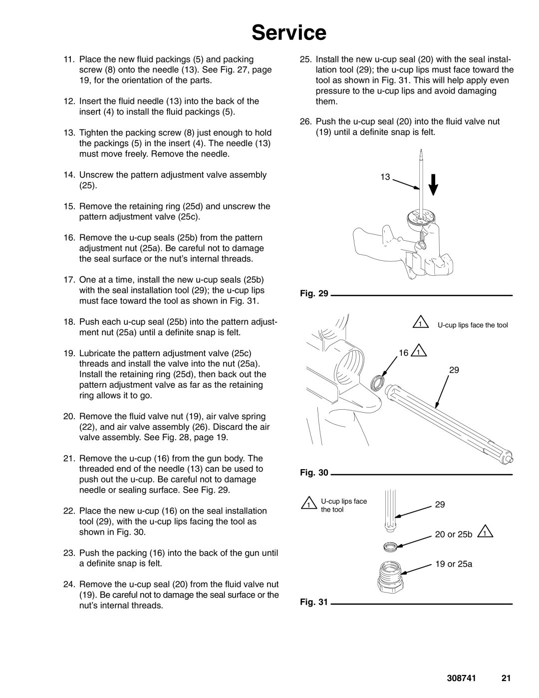
21.Remove the
22.Place the new
23.Push the packing (16) into the back of the gun until a definite snap is felt.
24.Remove the
25.Install the new
26.Push the
(19)until a definite snap is felt.
13
Fig. 29
1 |
161
29
Fig. 30
1 | 29 | ||
the tool | |||
|
|
20 or 25b 1
19 or 25a
Fig. 31