a.Graco WB100 Enclosure: Slide hose through the strain relief fitting (W). Ensure conductive layer (C) has passed through fitting. Tighten to 55
C
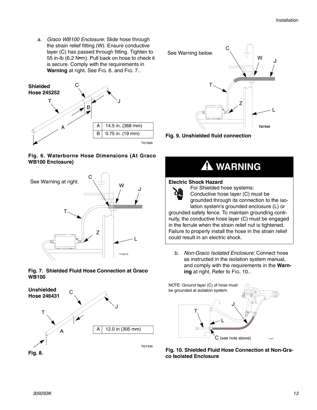
See Warning below.
W
Installation
J
Shielded C
Hose 245252
T
B
A
J
A14.5 in. (368 mm)
B0.75 in. (19 mm)
TI2166A
T
Z
L
TI2744A
Fig. 9. Unshielded fluid connection
Fig. 6. Waterborne Hose Dimensions (At Graco WB100 Enclosure)
![]() WARNING
WARNING
C
See Warning at right.
W
T
Z
J
Electric Shock Hazard
For Shielded hose systems: Conductive hose layer (C) must be grounded through its connection to the iso- lation system’s grounded enclosure (L) or
grounded safety fence. To maintain grounding conti- nuity, the conductive hose layer (C) must be engaged in the ferrule when the strain relief nut is tightened.
Failure to properly install the hose in the strain relief
L
TI1897A
Fig. 7. Shielded Fluid Hose Connection at Graco WB100
Unshielded |
| C |
Hose 246431 |
| |
|
| |
T |
| J |
|
| |
| A | A 12.0 in (305 mm) |
|
| |
|
| TI2743A |
Fig. 8. |
|
|
could result in an electric shock.
b.
NOTE: Ground layer (C) of hose must be grounded at isolation system.
J
T
![]() L
L
C (see note above) | TI1966A |
Fig. 10. Shielded Fluid Hose Connection at Non-Gra- co Isolated Enclosure
309293K | 13 |