Installation
Select a Fluid Nozzle and Air Cap
![]() WARNING
WARNING
Pressurized Equipment Hazard
To reduce the risk of an injury, follow the Pressure Relief Procedure on page 20 before removing or installing a fluid nozzle and/or air cap.
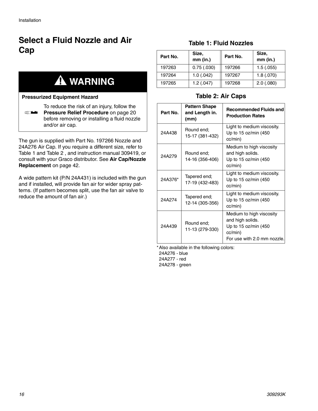
The gun is supplied with Part No. 197266 Nozzle and 24A276 Air Cap. If you require a different size, refer to Table 1 and Table 2 , and instruction manual 309419, or consult with your Graco distributor. See Air Cap/Nozzle Replacement on page 42.
A wide pattern kit (P/N 24A431) is included with the gun and if installed, will provide fan air for wider spray pat- terns. (If pattern becomes split, use the fan air valve to reduce the amount of fan air.)
Table 1: Fluid Nozzles
Part No. | Size, |
| Part No. | Size, |
mm (in.) |
| mm (in.) | ||
|
|
| ||
|
|
|
|
|
197263 | 0.75 (.030) |
| 197266 | 1.5 (.055) |
|
|
|
|
|
197264 | 1.0 (.042) |
| 197267 | 1.8 (.070) |
|
|
|
|
|
197265 | 1.2 (.047) |
| 197268 | 2.0 (.080) |
|
|
|
|
|
Table 2: Air Caps
| Pattern Shape | Recommended Fluids and | |
Part No. | and Length in. | ||
Production Rates | |||
| (mm) | ||
|
| ||
|
|
| |
| Round end; | Light to medium viscosity. | |
24A438 | Up to 15 oz/min (450 | ||
| cc/min) | ||
|
| ||
|
|
| |
|
| Medium to high viscosity | |
24A279 | Round end; | and high solids. | |
Up to 15 oz/min (450 | |||
| |||
|
| cc/min) | |
|
|
| |
| Tapered end; | Light to medium viscosity. | |
24A376* | Up to 15 oz/min (450 | ||
| cc/min) | ||
|
| ||
|
|
| |
| Tapered end; | Light to medium viscosity. | |
24A274 | Up to 15 oz/min (450 | ||
| cc/min) | ||
|
| ||
|
|
| |
|
| Medium to high viscosity | |
| Round end; | and high solids. | |
24A439 | Up to 15 oz/min (450 | ||
| cc/min) | ||
|
| ||
|
| For use with 2.0 mm nozzle. | |
|
|
| |
*Also available in the following colors: | |||
24A276 - blue |
| ||
24A277 - red |
| ||
24A278 - green |
| ||
16 | 309293K |
