Setup
Setup
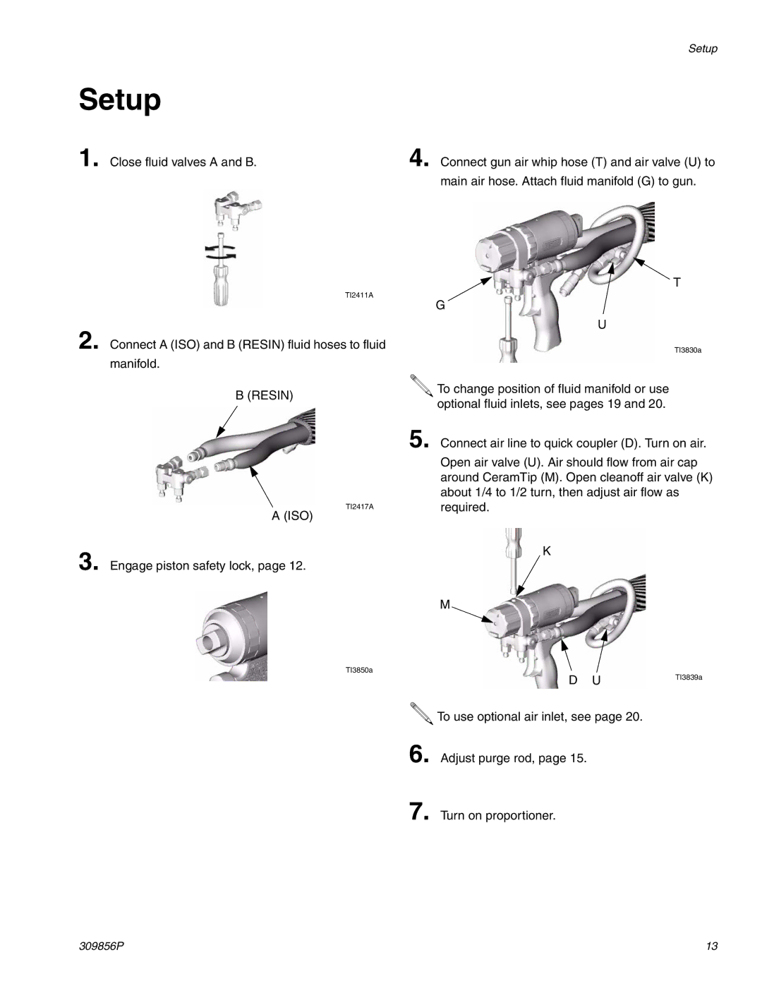
1. Close fluid valves A and B.
TI2411A
2. Connect A (ISO) and B (RESIN) fluid hoses to fluid manifold.
B (RESIN)
TI2417A
A (ISO)
3. Engage piston safety lock, page 12.
TI3850a
4. Connect gun air whip hose (T) and air valve (U) to
main air hose. Attach fluid manifold (G) to gun.
T
G
U
TI3830a
![]() To change position of fluid manifold or use optional fluid inlets, see pages 19 and 20.
To change position of fluid manifold or use optional fluid inlets, see pages 19 and 20.
5. Connect air line to quick coupler (D). Turn on air.
Open air valve (U). Air should flow from air cap around CeramTip (M). Open cleanoff air valve (K) about 1/4 to 1/2 turn, then adjust air flow as required.
K
M
D | U | TI3839a |
|
![]() To use optional air inlet, see page 20.
To use optional air inlet, see page 20.
6. Adjust purge rod, page 15.
7. Turn on proportioner.
309856P | 13 |
