Clean Slip-Fit Polycarballoy Mix Module
1. Follow Pressure Relief Procedure, page 18.
2. Flush Gun, page 22.
3. Remove mix module, page 38.
CAUTION
To avoid damaging mix module, do not force drill bits when cleaning impingement ports. Some ports are offset or angled.
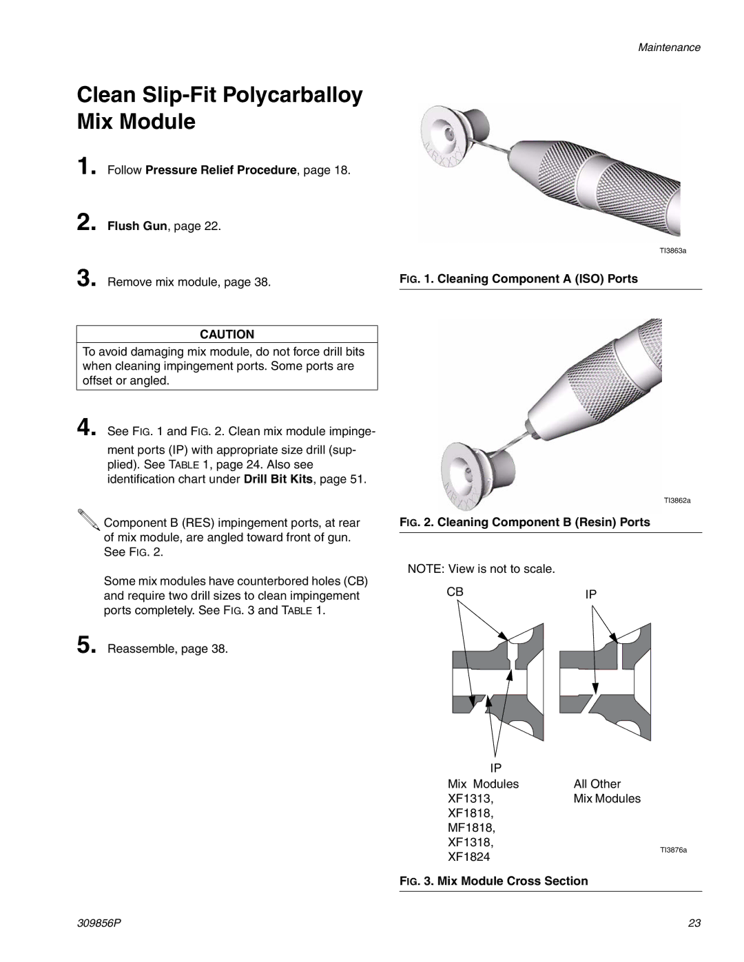
4. See FIG. 1 and FIG. 2. Clean mix module impinge-
ment ports (IP) with appropriate size drill (sup- plied). See TABLE 1, page 24. Also see identification chart under Drill Bit Kits, page 51.
![]() Component B (RES) impingement ports, at rear of mix module, are angled toward front of gun. See FIG. 2.
Component B (RES) impingement ports, at rear of mix module, are angled toward front of gun. See FIG. 2.
Some mix modules have counterbored holes (CB) and require two drill sizes to clean impingement ports completely. See FIG. 3 and TABLE 1.
5. Reassemble, page 38.
Maintenance
TI3863a
FIG. 1. Cleaning Component A (ISO) Ports
TI3862a
FIG. 2. Cleaning Component B (Resin) Ports
NOTE: View is not to scale.
CBIP
IP |
|
Mix Modules | All Other |
XF1313, | Mix Modules |
XF1818,
MF1818,
XF1318,
XF1824
TI3876a
FIG. 3. Mix Module Cross Section
309856P | 23 |
