Contents
Plural Component, Impingement Mix Mechanical Purge Spray Gun
Contents
Manual Conventions
Standard Round Pattern Guns
List of Models/Selection Guide
Pressure in psi MPa, bar
Standard Flat Pattern Guns
Flow Rate in gpm lpm
Direct Impingement Round Pattern Guns
Direct Impingement Flat Pattern Guns
Four-Hose Gun
Personal Protective Equipment
Fire and Explosion Hazard
Key
Overall View
Grounding
Piston Safety Lock
Isocyanate Hazard
Keep a and B Components Separate
ISO
Setup
Disengage piston safety lock,
1/4 Turn
Adjust Purge Rod
Adjust Flat CeramTip
Shutdown for More than a Day
Follow Pressure Relief Procedure,
Shutdown
Daily Shutdown
Pressure Relief Procedure
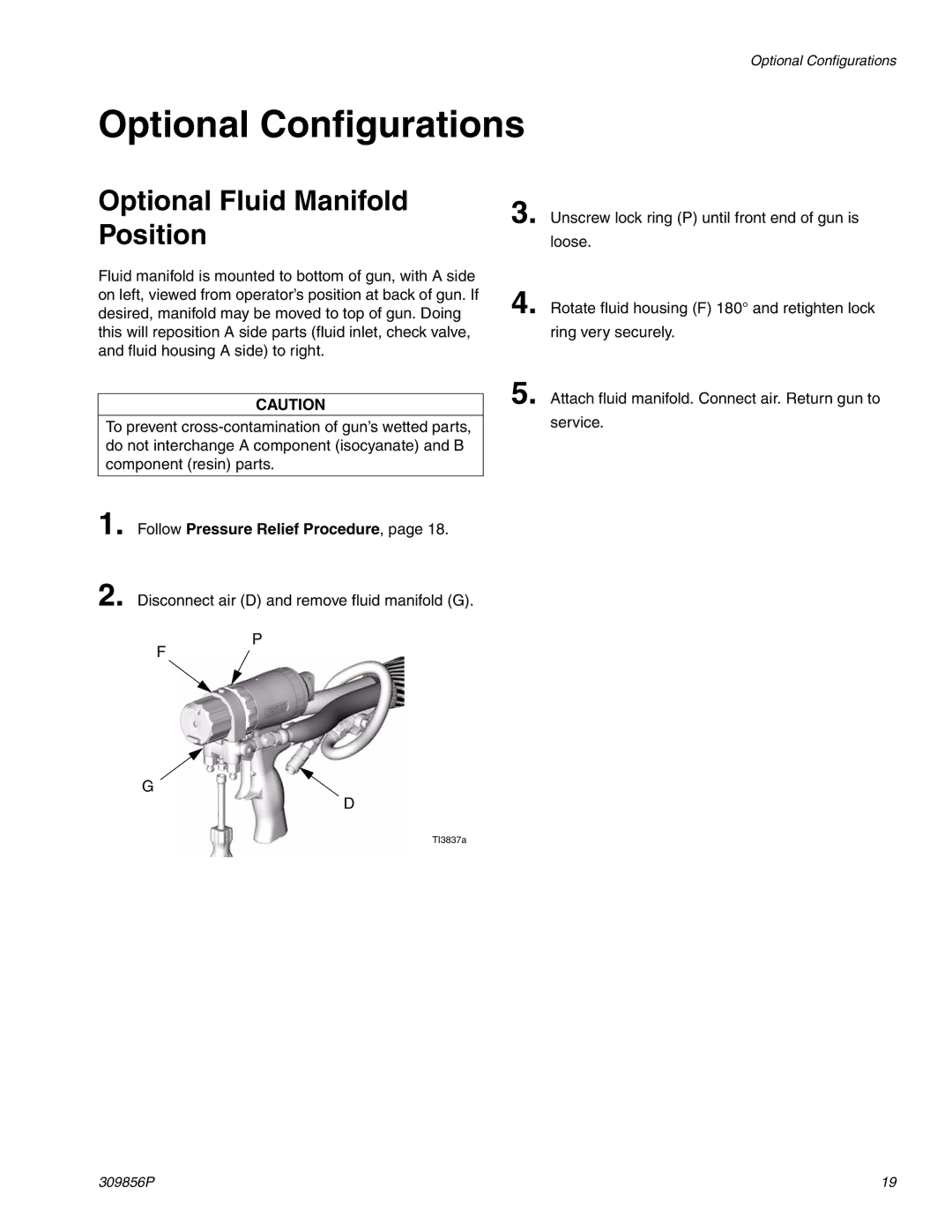
Optional Fluid Manifold Position
Optional Configurations
Air Hose
Follow Pressure Relief Procedure, page 18. Also
Optional Hose Position
Fluid Hoses
Maintenance
Clean Fluid Manifold
Clean Outside of Gun
Clean Air Cap
Clean Muffler
Cleaning Component a ISO Ports
Clean Slip-Fit Polycarballoy Mix Module
Impingement Port Drill Counterbore Drill
Impingement Port Cleanout Drill Sizes
XF1313 #81
Round CeramTip
Clean CeramTip
External Quick Cleaning Method
Cleanout Drill Sizes for Round CeramTips
Adjust Purge Rod,
Clean Purge Rod
Stuck Purge Rod
Reassemble Front End, Adjust Purge Rod,
Adjust Front Rod Seal
Disassemble Front End,
Adjust Rear Rod Seal
See Clean Purge Rod,
Troubleshooting
Adjust Rear Rod Seal,
Gun Triggered Fluid Spraying
Theory of Operation
Gun Detriggered Mechanical Purging
Cutaway View
Replace CeramTip
Repair
Tools Required
Lubrication
Disassemble Front End
Reassemble Front End
Adjust Purge Rod,
Slip-Fit Polycarballoy Mix Module
Attach fluid manifold. Return gun to service
Rear Rod Seal
Check Valves
Piston and Purge Rod
Install piston safety lock assembly until bottomed out
Air Valve
Piston Safety Lock
309856P
Flush Manifold Detail
Parts
Handle
Part No. Description Qty
Standard Flat Pattern Guns
Slip-Fit Polycarballoy Mix Module Kits
Slip-Fit Polycarballoy Mix Module Part Numbering Code
Standard Round Pattern Guns
Direct Impingement Flat Pattern Guns
Direct Impingement Round Pattern Guns
Flat CeramTips
CeramTip Kits
Round CeramTip Part Numbering Code
Flat CeramTip Part Numbering Code
Kit Part No Qty in Kit Drill Bit Size Illustration Nominal
Drill Bit Kits
Check Valve Filter Screen Kits 10 per kit
Gun Repair Kits
Accessories
Hose Adapter Kits
Solvent Flush Pail Kit
Pour Nozzle Kit
Category Data
Technical Data
Graco Information
Graco Standard Warranty
Toll Free