Installation
EQUIPMENT PACKAGING
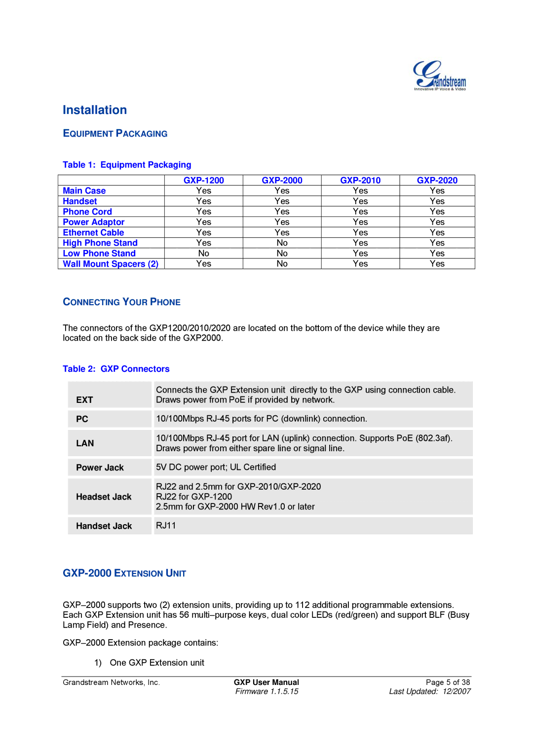
Table 1: Equipment Packaging
| ||||
Main Case | Yes | Yes | Yes | Yes |
Handset | Yes | Yes | Yes | Yes |
Phone Cord | Yes | Yes | Yes | Yes |
Power Adaptor | Yes | Yes | Yes | Yes |
Ethernet Cable | Yes | Yes | Yes | Yes |
High Phone Stand | Yes | No | Yes | Yes |
Low Phone Stand | No | No | Yes | Yes |
Wall Mount Spacers (2) | Yes | No | Yes | Yes |
CONNECTING YOUR PHONE
The connectors of the GXP1200/2010/2020 are located on the bottom of the device while they are located on the back side of the GXP2000.
Table 2: GXP Connectors
| EXT |
| Connects the GXP Extension unit directly to the GXP using connection cable. |
|
|
| Draws power from PoE if provided by network. |
| |
|
|
|
|
|
|
|
|
|
|
| PC |
| 10/100Mbps |
|
|
|
|
|
|
|
|
|
|
|
| LAN |
| 10/100Mbps |
|
|
| Draws power from either spare line or signal line. |
| |
|
|
|
| |
|
|
|
|
|
|
|
|
|
|
| Power Jack |
| 5V DC power port; UL Certified |
|
|
|
|
|
|
|
|
|
|
|
| Headset Jack |
| RJ22 and 2.5mm for |
|
|
| RJ22 for |
| |
|
|
| 2.5mm for |
|
|
|
|
|
|
|
|
|
|
|
| Handset Jack |
| RJ11 |
|
|
|
|
|
|
1) One GXP Extension unit
Grandstream Networks, Inc. | GXP User Manual | Page 5 of 38 |
| Firmware 1.1.5.15 | Last Updated: 12/2007 |