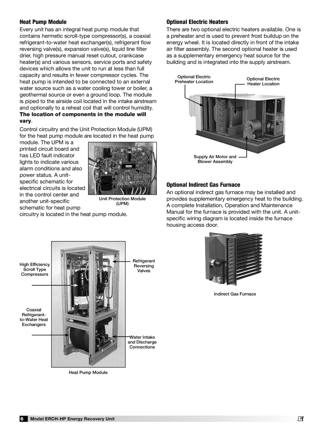
473501 specifications
Greenheck Fan 473501 is a significant player in the world of ventilation solutions, specifically designed to meet the increasing demands for efficiency and effectiveness in air movement. This commercial-grade fan is particularly noted for its high performance and reliability, making it a top choice for various applications, ranging from industrial settings to larger commercial spaces.One of the main features of the Greenheck 473501 is its energy-efficient design. It is engineered to minimize energy consumption while maximizing airflow, allowing users to achieve optimal performance without incurring high utility bills. The fan is equipped with a powerful motor that not only ensures consistent airflow but also contributes to its overall longevity and durability.
The fan boasts an impressive air performance rating, which is crucial for environments that require precise temperature and humidity control. With adjustable airflow settings, users can customize the fan’s operation to suit specific needs, whether that means circulating air in a warehouse or exhaust in a manufacturing facility.
Another standout characteristic is the fan's robust construction. Built with corrosion-resistant materials, the Greenheck 473501 is ideal for use in harsh environments, where exposure to moisture and other elements could compromise lesser fans. The design also incorporates noise-reducing technologies, making it suitable for settings where quiet operation is essential, such as schools, hospitals, and office buildings.
In terms of installation, the Greenheck 473501 is designed for versatility. It can be easily integrated into various ventilation systems, whether for new constructions or upgrades to existing infrastructure. Its compact footprint allows for convenient placement without sacrificing performance.
Furthermore, Greenheck offers extensive support and resources for this model, ensuring users have access to the information necessary for optimal operation, maintenance, and any potential troubleshooting.
Overall, the Greenheck Fan 473501 represents a harmonious blend of efficiency, durability, and flexibility, making it an ideal choice for those seeking a high-quality ventilation solution that meets contemporary environmental standards while delivering reliable performance across diverse applications.