SECTION 4: IDENTIFICATION
2
3
4 ![]()
5 ![]()
6
1
11
10
![]() 9
9
8
7
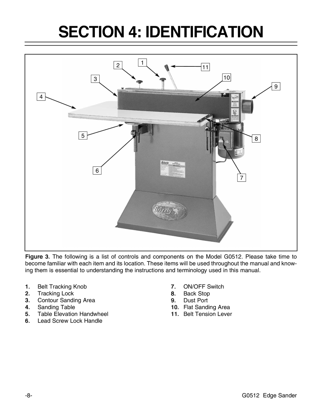
Figure 3. The following is a list of controls and components on the Model G0512. Please take time to become familiar with each item and its location. These items will be used throughout the manual and know- ing them is essential to understanding the instructions and terminology used in this manual.
1. | Belt Tracking Knob | 7. | ON/OFF Switch |
2. | Tracking Lock | 8. | Back Stop |
3. | Contour Sanding Area | 9. | Dust Port |
4. | Sanding Table | 10. | Flat Sanding Area |
5. | Table Elevation Handwheel | 11. | Belt Tension Lever |
6.Lead Screw Lock Handle
G0512 Edge Sander |